Typical Damage mechanisms in Refining industries
Mechanical and Metallurgical Failure Mechanisms
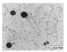
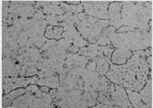
Graphitization is a change in the microstructure of certain carbon steels and 0.5Mo steels after long-term operation in the 430 to 600°C range that may cause a loss in strength, ductility, and/or creep resistance. At elevated temperatures, the carbide phases in these steels are unstable and may decompose into graphite nodules. This decomposition is known as graphitization. It usually affects carbon and 0.5 Mo steels.
The most important factors that affect graphitization are the chemistry, stress, temperature, and time of exposure. In general, graphitization is not commonly observed. Some steels are much more susceptible to graphitization than others, but exactly what causes some steels to graphitize while others are resistant is not well understood. It was originally thought that silicon and aluminum content played a major role but it has been shown that they have negligible influence on graphitization.
Graphitization has been found in low alloy C-Mo steels with up to 1% Mo. The addition of about 0.7% chromium has been found to eliminate graphitization. Temperature has an important effect on the rate of graphitization. Below 420°C, the rate is extremely slow. The rate increases with increasing temperature. There are two general types of graphitization. First is random graphitization in which the graphite nodules are distributed randomly throughout the steel. While this type of graphitization may lower the room-temperature tensile strength some, it does not usually lower the creep resistance. The second and more damaging type of graphitization results in chains or local planes of concentrated graphite nodules. This form of graphitization can result in a significant reduction in load bearing capacity while increasing the potential for brittle fracture along this plane. The two forms of this graphitization are weld heat affected zone graphitization and non-weld graphitization. Weld heat affected zone graphitization is most frequently found in the heat-affected zone adjacent to welds in a narrow band, corresponding to the low temperature edge of the heat affected zone.
In multipass welded butt joints, these zones overlap each other, covering the entire cross-section. Graphite nodules can form at the low temperature edge of these heat affected zones, resulting in a band of weak graphite extending across the section. Because of its appearance, this graphite formation within heat affected zones is called eyebrow graphitization. Non-weld graphitization is a form of localized graphitization that sometimes occurs along planes of localized yielding in steel. It also occurs in a chain-like manner in regions that have experienced significant plastic deformation because of cold working operations or bending.
The extent and degree of graphitization is usually reported in a qualitative fashion (none, slight, moderate, severe). Although it is difficult to predict the rate at which it forms, severe heat affected zone graphitization can develop in as little as 5 years at service temperatures above 540°C Very slight graphitization would be expected to be found after 30 to 40 years 450°C.
Graphitization is the decomposition of pearlite into ferrite and randomly dispersed graphite, which can result in embrittlement when the graphite particles form along a continuous zone through a load-carrying member. The degree of embrittlement depends on the distribution, size, and shape of the graphite. When the graphite is present in sufficient quantity and the inclusions are aligned or continuous, brittle fracture can occur along this relatively weak pure-iron/freecarbon interface. Continuous graphite formation is sometimes called chain graphitization. The severity of graphitization is frequently evaluated by bend testing.
Graphitization
Affected Units or Equipment
Primarily hot-wall piping and equipment in the FCC, catalytic reforming and coker units. Bainitic grades are less susceptible than coarse pearlitic grades. Few failures directly attributable to graphitization have been reported in the refining industry. However, graphitization has been found where failure resulted primarily from other causes. Several serious cases of graphitization have occurred in the reactors and piping of fluid catalytic cracking units, as well as with carbon steel furnace tubes in a thermal cracking unit and the failure of seal welds at the bottom tube sheet of the vertical boiler in a fluid catalytic cracker waste heat boiler. A graphitization failure was reported on a C-0.5Mo catalytic reformer reactor/interheater line long seam weld.
Where concentrated eyebrow graphitization occurs along heat affected zones, the creep rupture strength may be drastically lowered. Slight to moderate amounts of graphite along the heat-affected zones do not appear to significantly lower room or high-temperature properties. Graphitization seldom occurs on boiling surface tubing but did occur in low alloy C-0.5Mo tubes and headers during the 1940’s. Economizer tubing, steam piping and other equipment that operates in the range of temperatures of 440°C to 560°C is more likely to suffer graphitization. The addition of chromium together with other strong carbide formers, such as tungsten, vanadium, molybdenum, niobium, and titanium, tends to stabilize the carbide constituent so that it does not ultimately revert to graphite, but such carbides undergo progressive spheroidization and coalescence under suitable temperature environments.
Appearance or Morphology of Damage
Damage due to graphitization is not visible or readily apparent and can only be observed by metallographic examination Advanced stages of damage related to loss in creep strength may include microfissuring/microvoid formation, subsurface cracking or surface connected cracking.
Prevention / Mitigation
Graphitization can be prevented by using chromium containing low alloy steels for long-term operation above 430°C.
Inspection and Monitoring
Evidence of graphitization is most effectively evaluated through removal of full thickness samples for examination using metallographic techniques. Damage may occur midwall so that field replicas may be inadequate. Advanced stages of damage related to loss in strength include surface breaking cracks or creep deformation that may be difficult to detect.
Related Mechanisms
Spheroidization (softening) and graphitization are competing mechanisms that occur at overlapping temperature ranges. Spheroidization tends to occur preferentially above 550°C, while graphitization predominates below this temperature.
Spheroidization is a change in the microstructure of steels after exposure in the 440°C to 750°C range, where the carbide phases in carbon steels are unstable and may agglomerate from their normal plate-like form to a spheroidal form, or from small, finely dispersed carbides in low alloy steels like 1Cr-0.5Mo to large agglomerated carbides. Spheroidization may cause a loss in strength and/or creep resistance. It affects all commonly used grades of carbon steel and low to high alloy steels including C-0.5Mo, 1Cr-0.5Mo,1.25Cr-0.5Mo,2.25Cr-1Mo, 3Cr -1Mo, 5Cr-0.5Mo, and 9Cr-1Mo steels.
Metal chemistry, microstructure, exposure time, and temperature are critical factors. The rate of spheroidization depends on the temperature and initial microstructure. Spheroidization can occur in a few hours at higher temperatures, but may take several years at lower ones. Annealed steels are more resistant to spheroidization than normalized steels. Coarse-grained steels are more resistant than fine-grained. Fine grained silicon-killed steels are more resistant than aluminium killed.
Affected Units or Equipment
Spheroidization can occur in piping and equipment after exposure to temperatures above 450°C. The loss in strength may be as high as about 30% but failure is not likely to occur except under very high applied stresses, in areas of stress concentration, or in combination with other damage mechanisms. The loss in strength is usually accompanied by an increase in ductility which allows for deformation at stress concentrations. Spheroidization affects hot wall piping and equipment in the FCC, catalytic reforming and coker units. Fired heater tubes in boilers or process units may be affected by a loss in creep strength, but equipment, in general, is seldom renewed or repaired because of spheroidization.
Spehroidization
Appearance or Morphology of Damage
Spheroidization is not visible or readily apparent and can only be observed through metallography. The pearlitic phase undergoes a time dependant transformation from partial to complete spheroidization. In the case of the 5% to 9% CrMo alloys, spheroidization is the process of transforming the carbides from their original finely dispersed morphology to large agglomerated carbides.
Temper embrittlement is the reduction in toughness due to a metallurgical change that can occur in some low alloy steels as a result of long term exposure in the temperature range of about 340°C to 600°C . This change causes an upward shift in the ductile-to-brittle transition temperature as measured by Charpy impact testing. Although the loss of toughness is not evident at operating temperature, equipment that is temper embrittled may be susceptible to brittle fracture during start-up and shutdown.
Affected are primarily 2.25Cr-1Mo low alloy steel, 3Cr-1Mo (to a lesser extent), and the high-strength low alloy Cr-Mo-V rotor steels, as well as older generation 2.25Cr-1Mo materials manufactured prior to 1972 may be particularly susceptible. Some high strength low alloy steels are also susceptible. The C-0.5Mo and 1.25Cr-0.5Mo alloy steels are not significantly affected by temper embrittlement. However, other high temperature damage mechanisms promote metallurgical changes that can alter the toughness or high temperature ductility of these materials.
Alloy steel composition, thermal history, metal temperature and exposure time are critical factors. Susceptibility to temper embrittlement is largely determined by the presence of the alloying elements manganese and silicon, and the tramp elements phosphorus, tin, antimony, and arsenic. The strength level and heat treatment/fabrication history should also be considered. Temper embrittlement of 2.25Cr-1Mo steels develops more quickly at about 480°C than in the 430°C to 440°C range, but the damage is more severe after long-term exposure at 440°C. Some embrittlement can occur during fabrication heat treatments, but most of the damage occurs over many years of service in the embrittling temperature range. This form of damage will significantly reduce the structural integrity of a component containing a cracklike flaw. An evaluation of the materials toughness may be required depending on the flaw type, the severity of the environment, and the operating conditions, particularly in hydrogen service.
Affected Units or Equipment
Temper embrittlement occurs in a variety of process units after long term exposure to temperatures above 340°C. It should be noted that there have been very few industry failures related directly to temper embrittlement. Equipment susceptible to temper embrittlement is most often found in hydroprocessing units, particularly reactors, hot feed/effluent exchanger components, and hot HP separators. Other units with the potential for temper embrittlement include catalytic reforming units (reactors and exchangers), FCC reactors, coker and visbreaking units. Welds in these alloys are often more susceptible than the base metal and should be evaluated.
Appearance or Morphology of Damage
Temper embrittlement is a metallurgical change that is not readily apparent and can be confirmed through impact testing. Damage due to temper embrittlement may result in catastrophic brittle fracture. Temper embrittlement can be identified by an upward shift in the ductile-to-brittle transition temperature measured in a Charpy V-notch impact test, as compared to the non-embrittled or de-embrittled material. Another important characteristic of temper embrittlement is that there is no effect on the upper shelf energy.
Prevention / Mitigation for Existing Materials
Temper embrittlement cannot be prevented if the material contains critical levels of the embrittling impurity elements and is exposed in the embrittling temperature range. To minimize the possibility of brittle fracture during startup and shutdown, many refiners use a pressurization sequence to limit system pressure to about 25 percent of the maximum design pressure for temperatures below a Minimum Pressurization Temperature (MPT). MPT’s generally range from 170°C for the earliest, most highly temper embrittled steels, down to 60°C or lower for newer, temper embrittlement resistant steels (as required to also minimize effects of hydrogen embrittlement). If weld repairs are required, the effects of temper embrittlement can be temporarily reversed (deembrittled) by heating at 620°C for 2 hours per inch of thickness, and rapidly cooling to room temperature. It is important to note that re-embrittlement will occur over time if the material is re-exposed to the embrittling temperature range.
Prevention / Mitigation for New Materials
The best way to minimize the likelihood and extent of temper embrittlement is to limit the acceptance levels of manganese, silicon, phosphorus, tin, antimony, and arsenic in the base metal and welding consumables. In addition, strength levels and PWHT procedures should be specified and carefully controlled.
A common way to minimize temper embrittlement is to limit the "J*" Factor for base metal and the "X" Factor for weld metal, based on material composition as follows:
J* = (Si + Mn) x (P + Sn) x 104 {elements in wt%}
X =(10P + 5Sb + 4Sn + As)/100 {elements in ppm}
Typical J* and X factors used for 2.25 Cr steel are 100 and 15, respectively. Studies have also shown that limiting the (P + Sn) to less than 0.01% is sufficient to minimize temper embrittlement because (Si + Mn) control the rate of embrittlement.
Expert metallurgical advice should be solicited to determine acceptable composition, toughness and strength levels, as well as appropriate welding, fabricating and heat treating procedures for new low alloy steel heavy wall equipment and low alloy equipment operating in the creep range.
Inspection and Monitoring
A common method of monitoring is to install blocks of original heats of the alloy steel material inside the reactor. Samples are periodically removed from these blocks for impact testing to monitor progress of temper embrittlement or until a major repair issue arises. Process conditions should be monitored to ensure that a proper pressurization sequence is followed to help prevent brittle fracture due to temper embrittlement.
The effect of temper embrittlement on the fracture toughness of a 1CrMoV steel
Strain aging is a form of damage found mostly in older carbon steels and C-0.5 Mo low alloy steels under the combined effects of deformation and aging at an intermediate temperature. This results in an increase in hardness and strength with a reduction in ductility and toughness. Affected steels are mostly older (pre-1980’s) carbon steels with a large grain size and C-0.5 Mo low alloy steel.
If low-carbon steel is deformed, its hardness and strength will increase upon aging at room or slightly elevated temperature. Strain-age embrittlement occurs when uncombined interstitial solute atoms, usually carbon and nitrogen, diffuse to dislocations and lattice discontinuities. The ordering of carbon and nitrogen atoms at the dislocations assists in the pinning of dislocations and thus causes an increase in strength and lowering of ductility.
Steel composition and manufacturing process determine steel susceptibility. Steels manufactured by the Bessemer or open hearth process contain higher levels of critical impurity elements than newer steels manufactured by the Basic Oxygen Furnace (BOF) process. In general, steels made by BOF and fully killed with aluminium will not be susceptible. The effect is found in rimmed and capped steels with higher levels of nitrogen and carbon, but not in the modern fully killed carbon steels manufactured to a fine grain practice.
Strain aging effects are observed in materials that have been cold worked and placed into service at intermediate temperatures without stress relieving. Strain aging is a major concern for equipment that contains cracks. If susceptible materials are plastically deformed and exposed to intermediate temperatures, the zone of deformed material may become hardened and less ductile. This phenomenon has been associated with several vessels that have failed by brittle fracture.
The pressurization sequence versus temperature is a critical issue to prevent brittle fracture of susceptible materials. Strain aging can also occur when welding in the vicinity of cracks and notches in a susceptible material.
Strain aging is most likely to occur in wall vessels manufactured from susceptible materials that have not been stress relieved.
Strain aging can result in the formation of brittle cracks that are revealed through detailed metallurgical analyses, but damage most likely will not be identified as strain aging until fracture has already occurred.
Prevention / Mitigation
Strain aging is not an issue for newer steels that contain low levels of interstitial impurity elements and sufficient aluminium (>0.015 wt%) to fully deoxidize the steel. For older equipment, extra care should be taken to avoid the potentially damaging effects of strain aging by avoiding stressing or pressurizing equipment until the metal temperature reaches an acceptable level where the risk of brittle fracture is low. Refer to curve “A” in UCS 66 of the ASME Code Section VIII, Division I for pressurization temperatures of vessels susceptible to strain aging effects. Applying PWHT to weld repairs of susceptible materials will eliminate the effects of strain aging. Where PWHT is not possible, buttering should be considered to minimize welding on old material under restraint.
Inspection and Monitoring
Inspection and monitoring are not used to control strain aging.
When deformation occurs at the intermediate temperature, the mechanism is referred to as dynamic strain aging. Blue brittleness is another form of strain aging.
885°F (475°C) embrittlement is a loss in toughness due to a metallurgical change that can occur in alloys containing a ferrite phase, as a result of exposure in the temperature range 320°C to 540°C.
It affects 400 Series SS (e.g., 405, 409, 410, 410S, 430, and 446). Duplex stainless steels such as Alloys 2205, 2304, and 2507. Wrought and cast 300 Series SS containing ferrite, particularly welds and weld overlay
Critical factor is the alloy composition, particularly chromium content, amount of ferrite phase, and operating temperature are critical factors. Increasing amounts of ferrite phase increase susceptibility to damage when operating in the high temperature range of concern. A dramatic increase in the ductile-to-brittle transition temperature will occur. A primary consideration is operating time at temperature within the critical temperature range. Damage is cumulative and results from the precipitation of an embrittling intermetallic phase that occurs most readily at approximately 475°C. Additional time is required to reach maximum embrittlement at temperatures above or below 475°C) For example, many thousands of hours may be required to cause embrittlement at 320°C. Since this type of embrittlement can occur in a relatively short period of time, it is often assumed that susceptible materials that have been exposed to temperatures in the 370°C to 540°C range are affected. The effect on toughness is not pronounced at the operating temperature, but is significant at lower temperatures experienced during plant shutdowns, startups or upsets. Embrittlement can result from tempering at higher temperatures or by holding within or cooling through the transformation range.
Affected Units or Equipment
This type of embrittlement can be found in any unit where susceptible alloys are exposed to the embrittling temperature range. Most refining companies limit the use of ferritic stainless steels to non-pressure boundary applications because of this damage mechanism. Common examples include fractionator trays and internals in high temperature vessels used in FCC, crude, vacuum and coker units. Typical failures include cracking when attempting to weld or to straighten bent, upset tower trays of Type 409 and 410 material (occurs often with vacuum tower trays of this material). Other examples include duplex stainless steel heat exchanger tubes and other components exposed to temperatures above 320°C for extended time periods.
Appearance or Morphology of Damage
This type of embrittlement is a metallurgical change that is not readily apparent with metallography but can be confirmed through bend or and impact testing. The existence of embrittlement can be identified by an increase in hardness in affected areas. Failure during bend testing or impact testing of samples removed from service is the most positive indicator of embrittlement.
Prevention / Mitigation
The best way to prevent embrittlement is to use low ferrite or non-ferritic alloys, or to avoid exposing the susceptible material to the embrittling range. It is possible to minimize the effects of embrittlement through modifications in the chemical composition of the alloy, however, resistant material may not always be readily available in most commercial forms. Embrittlement is reversible by heat treatment to dissolve precipitates, followed by rapid cooling. The de-embrittling heat treatment temperature is typically 600°C or higher and may not be practical for many equipment items. If the de-embrittled component is exposed to the same service conditions it will re-embrittle faster than it did initially.
Inspection and Monitoring
Impact or bend testing of samples removed from service is the most positive indicator of a problem. Most cases of embrittlement are found in the form of cracking during turnarounds, or during startup or shutdown when the material is below about 100°C and the effects of embrittlement are most detrimental. An increase in hardness is another method of evaluating the embrittlement.
Formation of a metallurgical phase known as sigma phase can result in a loss of fracture toughness in some stainless steels as a result of high temperature exposure. Affected Materials are 300 Series SS wrought metals, weld metal, and castings. Cast 300 Series SS including the HK and HP alloys are especially susceptible to sigma formation because of their high (10-40%) ferrite content. The 400 Series SS and other ferritic and martensitic SS with 17% Cr or more are also susceptible (e.g., Types 430 and 440)and duplex stainless steels.
Alloy composition, time and temperature are the critical factors. In susceptible alloys, the primary factor that affects sigma phase formation is the time of exposure at elevated temperature. Sigma phase occurs in ferritic (Fe-Cr), martensitic (Fe-Cr), austenitic (Fe-Cr-Ni) and duplex stainless steels when exposed to temperatures in the range 540°C to 1000°C. Embrittlement can result by holding within or cooling through the transformation range. Sigma forms most rapidly from the ferrite phase that exists in 300 Series SS and duplex SS weld deposits. It can also form in the 300 Series SS base metal (austenite phase) but usually more slowly. The 300 Series SS can exhibit about 10% to 15% sigma phase. Cast austenitic stainless steels can develop considerablly more sigma. Formation of sigma phase in austenitic stainless steels can also occur in a few hours, as evidenced by the known tendency for sigma to form if an austenitic stainless steel is subjected to a postweld heat treatment at 690°C. The tensile and yield strength of sigmatized stainless steels increases slightly compared with solution annealed material. This increase in strength is accompanied by a reduction in ductility (measured by percent elongation and reduction in area) and a slight increase in hardness. Stainless steels with sigma can normally withstand normal operating stresses, but upon cooling to temperatures below about 500oF (260oC) may show a complete lack of fracture toughness as measured in a Charpy impact test. The metallurgical change is actually the precipitation of a hard, brittle intermetallic compound that can also render the material more susceptible to intergranular corrosion. The precipitation rate increases with increasing chromium and molybdenum content.
Affected Units or Equipment
Common examples include stainless steel cyclones, piping ductwork and valves in high temperature FCC Regenerator service. 300 Series SS weld overlays and tube-to-tubesheet attachment welds can be embrittled during PWHT treatment of the underlying CrMo base metal. Stainless steel heater tubes are susceptible and can be embrittled.
Appearance or Morphology of Damage
Sigma phase embrittlement is a metallurgical change that is not readily apparent, and can only be confirmed through metallographic examination and impact testing. Damage due to sigma phase embrittlement appears in the form of cracking, particularly at welds or in areas of high restraint. Tests performed on sigmatized 300 Series SS (304H) samples from FCC regenerator internals have shown that even with 10% sigma formation, the Charpy impact toughness was 53 J at 650°C. For the 10% sigmatized specimen, the values ranged from 0% ductility at room temperature to 100% at 650°C. Thus, although the impact toughness is reduced at high temperature, the specimens broke in a 100% ductile fashion, indicating that the wrought material is still suitable at operating temperatures. Cast austenitic stainless steels typically have high ferrite/sigma content (up to 40%) and may have very poor high temperature ductility.
Prevention / Mitigation
The best way to prevent sigma phase embrittlement is to use alloys that are resistant to sigma formation or to avoid exposing the material to the embrittling range. The lack of fracture ductility at room temperature indicates that care should be taken to avoid application of high stresses to sigmatized materials during shutdown, as a brittle fracture could result. The 300 Series SS can be de-sigmatized by solution annealing at 1950°F (1066°C) for four hours followed by a water quench. However, this is not practical for most equipment. Sigma phase in welds can be minimized by controlling ferrite in the range of 5% to 9% for Type 347 and somewhat less ferrite for Type 304. The weld metal ferrite content should be limited to the stated maximum to minimize sigma formation during service or fabrication, and must meet the stated minimum in order to minimize hot short cracking during welding. For stainless steel weld overlay clad Cr-Mo components, the exposure time to PWHT temperatures should be limited wherever possible.
Inspection and Monitoring
Physical testing of samples removed from service is the most positive indicator of a problem. Most cases of embrittlement are found in the form of cracking in both wrought and cast (welded) metals during turnarounds, or during startup or shutdown when the material is below about 260°C and the effects of embrittlement are most pronounced.
Brittle fracture is the sudden rapid fracture under stress (residual or applied) where the material exhibits little or no evidence of ductility or plastic deformation. Carbon steels and low alloy steels are of prime concern, particularly older steels. 400 Series SS are also susceptible.
When the critical combination of three factors is reached, brittle fracture can occur:
i) The materials’ fracture toughness (resistance to crack like flaws) as measured in a Charpy impact test;
ii) The size, shape and stress concentration effect of a flaw;
The amount of residual and applied stresses on the flaw.
Susceptibility to brittle fracture may be increased by the presence of embrittling phases. Steel cleanliness and grain size have a significant influence on toughness and resistance to brittle fracture. Thicker material sections also have a lower resistance to brittle fracture due to higher constraint which increases triaxial stresses at the crack tip. In most cases, brittle fracture occurs only at temperatures below the Charpy impact transition temperature (or ductile-to-brittle transition temperature), the point at which the toughness of the material drops off sharply.
Affected Units or Equipment
Equipment manufactured to the ASME Boiler and Pressure Vessel Code, Section VIII, Division 1, prior to the December 1987 Addenda, were made with limited restrictions on notch toughness for vessels operating at cold temperatures. However, this does not mean that all vessels fabricated prior to this date will be subject to brittle fracture. Many designers specified supplemental impact tests on equipment that was intended to be in cold service. Equipment made to the same code after this date were subject to the requirements of UCS 66 (impact exemption curves). Most processes run at elevated temperature so the main concern is for brittle fracture during startup, shutdown, or hydrotest/tightness testing. Thick wall equipment on any unit should be considered. Brittle fracture can also occur during an autorefrigeration event in units processing light hydrocarbons such as methane, ethane/ethylene, propane/propylene, or butane. This includes alkylation units, olefin units and polymer plants (polyethylene and polypropylene). Storage bullets/spheres for light hydrocarbons may also be susceptible. Brittle fracture can occur during ambient temperature hydrotesting due to high stresses and low toughness at the testing temperature.
Appearance or Morphology of Damage
Cracks will typically be straight, non-branching, and largely devoid of any associated plastic deformation (no shear lip or localized necking around the crack). Microscopically, the fracture surface will be composed largely of cleveage, with limited intergranular cracking and very little microvoid coalescence.
Prevention / Mitigation
For new equipment, brittle fracture is best prevented by using materials specifically designed for low temperature operation including upset and autorefrigeration events. Materials with controlled chemical composition, special heat treatment and impact test verification may be required. Refer to UCS 66 in Section VIII of the ASME BPV Code. Brittle fracture is an “event” driven damage mechanism. For existing materials, where the right combination of stress, material toughness and flaw size govern the probability of the event, an engineering study can be performed in accordance with API RP 579, Section 3, Level 1 or 2. Preventative measures to minimize the potential for brittle fracture in existing equipment are limited to controlling the operating conditions (pressure, temperature), minimizing pressure at ambient temperatures during startup and shutdown, and periodic inspection at high stress locations. Some reduction in the likelihood of a brittle fracture may be achieved by:
i) Performing a post weld heat treatment (PWHT) on the vessel if it was not originally done during manufacturing; or if the vessel has been weld repaired/modified while in service without the subsequent PWHT.
Perform a “warm” pre-stress hydrotest followed by a lower temperature hydrotest to extend the Minimum Safe Operating Temperature (MSOT) envelope.
Inspection and Monitoring
Inspection is not normally used to mitigate brittle fracture. Susceptible vessels should be inspected for pre-existing flaws/defects.
Related mechanisms are temper embrittlement, strain age embrittlement, 885F (475°C) embrittlement, titanium hydriding and sigma embrittlement.
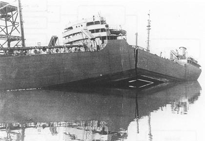
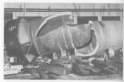
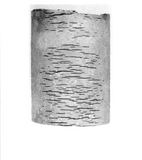
Example of brittle fracture of welded ship structure. S.S. Schenectady, which fractured at its outfitting dock, was one of 19 Liberty ships that experienced brittle cracking of the welded structure.
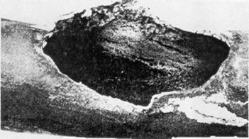
Classic example of brittle fracture that occurred during hydrotest (Reference API 571)
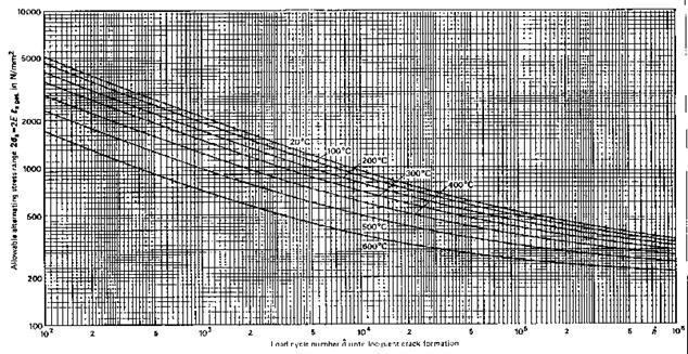
At high temperatures, metal components can slowly and continuously deform under load below the yield stress. This time dependent deformation of stressed components is known as creep. Deformation leads to damage that may eventually lead to a rupture.
Development of creep strain and creep strain rate over time and schematic illustration of micro structural changes in material
During the phase of primary creep, the creep strain rate decreases, and the main cause of this phenomenon is seen in the increase of density of dislocations in the material. In the phase of secondary creep, a balance of hardening and softening mechanisms is present; therefore the creep strain rate is almost constant. Aside from changes in the micro structure like formation of precipitates, other thermally activated processes in the microstructure can take place like: Pearlite decomposition, coagulation and precipitation of carbides etc. These processes are independent from material, time and temperature. All the changes in the microstructure up to this point are reversible, and their effects can be mitigated trough i.e. heat treatment.
Irreversible creep damage appears in the form of cavities, dependent on material and load (stress, temperature and time). In connection with the metallurgical changes (sub-grain growth, particle coarsening and increase of particle distances), the creep strain rate increases significantly. As the damage progresses, chains of cavities appear mostly on the grain boundaries, as well as micro cracks. They tend to grow in the direction of load. This phase is known as tertiary creep phase.
The optical-microscope visible damage in the form of creep cavities is dependent on type of material and its microstructure, temperature and load (stress and multiaxiality). Multiaxiality of the load reduces the deformability of the material, therefore promoting the cavitations processes.
The rate of creep deformation is a function of the material, load, and temperature. The rate of damage (strain rate) is sensitive to both load and temperature. Generally, an increase of about 10°C or an increase of 15% on stress can cut the remaining life in half or more, depending on the alloy. If the metal temperature exceeds the values of about 400-500°C, then creep damage and creep cracking can occur. The level of creep damage is a function of the material and the coincident temperature/stress level at which the creep deformation occurs. The life of metal components becomes nearly infinite at temperatures below the threshold limit, given for each group of materials, even at the high stresses near a crack tip. The appearance of creep damage with little or no apparent deformation is often mistakenly referred to as creep embrittlement, but usually indicates that the material has low creep ductility. Low creep ductility is:
i) More severe for higher tensile strength materials and welds.
ii) More prevalent at the lower temperatures in the creep range, or low stresses in the upper creep range.
iii) More likely in a coarse-grained material than a fine-grained material.
iv) Not evidenced by a deterioration of ambient temperature properties.
v) Promoted by certain carbide types in some CrMo steels.
i) g) Increased stress due to loss in thickness from corrosion will reduce time to failure.
Affected Units or Equipment
Creep damage is found in high temperature equipment operating above the creep range (material dependent). Heater tubes in fired heaters are especially susceptible as well as tube supports, hangers and other furnace internals. Piping and equipment, such as hot-wall catalytic reforming reactors and furnace tubes, hydrogen reforming furnace tubes, hot wall FCC reactors, FCC main fractionator and regenerator internals all operate in or near the creep range. Low creep ductility failures have occurred in weld Heat Affected Zones (HAZ) at nozzles and other high stress areas on catalytic reformer reactors. Cracking has also been found at long seam welds in some high temperature piping and in reactors on catalytic reformers. Welds joining dissimilar materials (ferritic to austenitic welds) may suffer creep related damage at high temperatures due to differential thermal expansion stresses.
Appearance or Morphology of Damage
The initial stages of creep damage can only be identified by scanning electron microscope metallography. Creep voids typically show up at the grain boundaries and in later stages form fissures and then cracks. At temperatures well above the threshold limits, noticeable deformation may be observed. For example, heater tubes may suffer long term creep damage and exhibit significant bulging before final fracture occurs. The amount of deformation is highly dependent on the material, and the combination of temperature and stress level. In vessels and piping, creep cracking can occur where high metal temperatures and stress concentrations occur together, such as near major structural discontinuities including pipe tee joints, nozzles, or welds at flaws. Creep cracking, once initiated, can progress rapidly.
Prevention / Mitigation
There is little that inspectors or operators can do to prevent this damage once a susceptible material has been placed into creep service, other than to minimize the metal temperature, particularly with fired heater tubes. Avoiding stress concentrators is important during design and fabrication. Low creep ductility can be minimized by the careful selection of chemistry for low alloy materials. Higher post weld heat treatment temperatures may help minimize creep cracking of materials with low creep ductility such as 1.25Cr-0.5Mo. Creep damage is not reversible. Once damage or cracking is detected much of the life of the component has been used up and typically the options are to repair or replace the damaged component. Higher PWHT in some cases can produce a more creep ductile material with longer life.
Equipment – Repair of creep damaged catalytic reformer reactor nozzles has been successfully accomplished by grinding out the affected area (making sure all the damaged metal is removed), re-welding and careful blend grinding to help minimize stress concentration. PWHT temperatures must be carefully selected and may require a higher PWHT than originally specified.
Fired Heater Tubes: alloys with improved creep resistance may be required for longer life. Heaters should be designed and operated to minimize hot spots and localized overheating. Visual inspection followed by thickness measurements and or strap readings may be required to assess remaining life of heater tubes in accordance with API RP 579. Minimizing process side fouling/deposits and fire side deposits/scaling can maximise tube life.
Creep damage with the associated microvoid formation, fissuring and dimensional changes is not effectively found by any one inspection technique. A combination of techniques (UT, RT, EC, dimensional measurements and replication) should be employed. Destructive sampling and metallographic examination are used to confirm damage. For pressure vessels, inspection should focus on welds of CrMo alloys operating in the creep range. The 1 Cr-0.5Mo and 1.25Cr-0.5Mo materials are particularly prone to low creep ductility. Most inspections are performed visually and followed by PT or WFMT on several-year intervals. Angle beam (shear wave) UT can also be employed, although the early stages of creep damage are very difficult to detect. Initial fabrication flaws should be mapped and documented for future reference. Fired heater tubes should be inspected for evidence of overheating, corrosion, and erosion as follows:
i) Tubes should be VT examined for bulging, blistering, cracking, sagging, and bowing.
ii) Wall thickness measurements of selected heater tubes should be made where wall losses are most likely to occur.
iii) Tubes should be examined for evidence of diametric growth (creep) with a strap or go/no go gauge, and in limited cases by metallography on in place replicas or tube samples. However, metallography on the OD of a component may not provide a clear indication of subsurface damage.
iv) Retirement criteria based on diametric growth and loss of wall thickness is highly dependent on the tube material and the specific operating conditions.
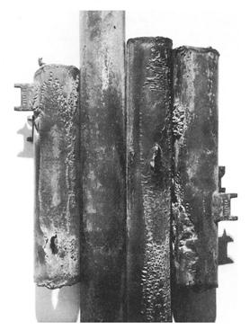
Examples of creep failures
Thermal fatigue is the result of cyclic stresses caused by variations in temperature. Damage is in the form of cracking that may occur anywhere in a metallic component where relative movement or differential expansion is constrained, particularly under repeated thermal cycling. Affects all materials of construction.
Key factors affecting thermal fatigue are the magnitude of the temperature swing and the frequency (number of cycles). Time to failure is a function of the magnitude of the stress and the number of cycles and decreases with increasing stress and increasing cycles. Startup and shutdown of equipment increase the susceptibility to thermal fatigue. There is no set limit on temperature swings; however, as a practical rule, cracking may be suspected if the temperature swing exceeds about 100°C. Damage is also promoted by rapid changes in surface temperature that result in a thermal gradient through the thickness or along the length of a component. For example: cold water on a hot tube (thermal shock); rigid attachments and a smaller temperature differential; inflexibility to accommodate differential expansion. Notches (such as the toe of a weld) and sharp corners (such as the intersection of a nozzle with a vessel shell) and other stress concentrations may serve as initiation sites.
Affected Units or Equipment
Examples include the mix points of hot and cold streams such as locations where condensate comes in contact with steam systems, such as de-superheating or attemperating equipment. Thermal fatigue cracking has been a major problem in coke drum shells. Thermal fatigue can also occur on coke drum skirts where stresses are promoted by a variation in temperature between the drum and skirt In steam generating equipment, the most common locations are at rigid attachments between neighboring tubes in the superheater and reheater. Slip spacers designed to accommodate relative movement may become frozen and act as a rigid attachment when plugged with fly ash. Tubes in the high temperature superheater or reheater that penetrate through the cooler waterwall tubes may crack at the header connection if the tube is not sufficiently flexible. These cracks are most common at the end where the expansion of the header relative to the waterwall will be greatest. Steam actuated soot blowers may cause thermal fatigue damage if the first steam exiting the soot blower nozzle contains condensate. Rapid cooling of the tube by the liquid water will promote this form of damage. Similarly, water lancing or water cannon use on waterwall tubes may have the same effect.
Appearance or Morphology of Damage
Thermal fatigue cracks usually initiate on the surface of the component. They are generally wide and often filled with oxides due to elevated temperature exposure. Cracks may occur as single or multiple cracks. Thermal fatigue cracks propagate transverse to the stress and they are usually dagger-shaped, transgranular, and oxide filled. However, cracking may be axial or circumferential, or both, at the same location.
In steam generating equipment, cracks usually follow the toe of the fillet weld, as the change in section thickness creates a stress raiser (Figure 4-15). Cracks often start at the end of an attachment lug and if there is a bending moment as a result of the constraint, they will develop into circumferential cracks into the tube. Water in soot blowers may lead to a crazing pattern. The predominant cracks will be circumferential and the minor cracks will be axial.
Prevention / Mitigation
Thermal fatigue is best prevented through design and operation to minimize thermal stresses and thermal cycling. Several methods of prevention apply depending on the application.
i) Designs that incorporate reduction of stress concentrators, blend grinding of weld profiles, and smooth transitions should be used.
ii) Controlled rates of heating and cooling during startup and shutdown of equipment can lower stresses.
iii) Differential thermal expansion between adjoining components of dissimilar materials should be considered.
Designs should incorporate sufficient flexibility to accommodate differential expansion.
i) In steam generating equipment, slip spacers should slip and rigid attachments should be avoided.
ii) Drain lines should be provided on soot-blowers to prevent condensate in the first portion of the soot blowing cycle.
i) c) In some cases, a liner or sleeve may be installed to prevent a colder liquid from contacting the hotter pressure boundary wall
Inspection and Monitoring
Since cracking is usually surface connected, visual examination, MT and PT are effective methods of inspection. External SWUT inspection can be used for non-intrusive inspection for internal cracking and where reinforcing pads prevent nozzle examination. Heavy wall reactor internal attachment welds can be inspected using specialized ultrasonic techniques.
Thermal shock crack – left side alloy metal, right-side weld
Older fatigue crack fill with oxide
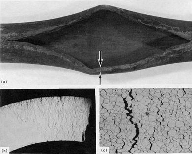
Typical thermal fatigue/thermal shock damage
Permanent deformation occurring at relatively low stress levels as a result of localized overheating. This usually results in bulging and eventually failure by stress rupture. It can occur in all fired heater tube materials and common materials of construction.
Temperature, time and stress are critical factors. Usually due to flame impingement or local overheating. Time to failure will increase as internal pressures or loading decrease. However, bulging and distortion can be significant at low stresses, as temperatures increase. Local overheating above the design temperature. Loss in thickness due to corrosion will reduce time to failure by increasing the stress.
Local overheating is usually much higher than the usual operating temperature, i.e. in the ranges well above 400-500°C for typical steels used in the process or power industry. The damage mechanism is tightly linked with the creep phenomena, i.e. underlying micro-structural mechanisms are the same.
Affected Units or Equipment
All boiler and fired heater tubes are susceptible. Furnaces with coking tendencies such as crude, vacuum, heavy oil hydroprocessing and coker units are often fired harder to maintain heater outlet temperatures and are more susceptible to localized overheating.
Hydroprocessing reactors may be susceptible to localized overheating of reactor beds due to inadequate hydrogen quench or flow maldistribution. Refractory lined equipment in the FCC, sulfur plant and other units may suffer localized overheating due to refractory damage and/or excessive firing.
Damage is typically characterized by localized deformation or bulging on the order of 3% to 10% or more, depending on the alloy, temperature and stress level. Ruptures are characterized by open “fishmouth” failures and are usually accompanied by thinning at the fracture surface
Prevention / Mitigation
Minimize localized temperature excursions. Fired heaters require proper burner management and fouling/deposit control to minimize hot spots and localized overheating. Utilize burners which produce a more diffuse flame pattern. In hydroprocessing equipment, install and maintain bed thermocouples in reactors and minimize the likelihood of hot spots through proper design and operation. Maintain refractory in serviceable condition in refractory lined equipment.
Inspection and Monitoring
In fired heaters, visual observation, IR monitoring of tubes and tubeskin thermocouples are used to monitor temperatures. Refractory lined equipment can be monitored with heat indicating paint and periodic IR scans. Inspect for refractory damage during shutdowns. Maintain and monitor reactor bed thermocouples as well as reactor skin thermocouples.
Overheating example - ASME SA-213, grade TP321H superheater tube that failed by thick-lip stress rupture
The operation of steam generating equipment is a balance between the heat flow from the combustion of the fuel and the generation of steam within the waterwall or generating tube. The flow of heat energy through the wall of the tube results in the formation of discrete steam bubbles (nucleate boiling) on the ID surface. The moving fluid sweeps the bubbles away. When the heat flow balance is disturbed, individual bubbles join to form a steam blanket, a condition known as Departure From Nucleate Boiling (DNB). Once a steam blanket forms, tube rupture can occur rapidly, as a result of short term overheating, usually within a few minutes.
Heat flux and fluid flow are critical factors. Flame impingement from misdirected or damaged burners can provide a heat flux greater than the steam generating tube can accommodate. On the water side, anything that restricts fluid flow (for example, pinhole leaks lower in the steam circuit or dented tubes from slag falls) will reduce fluid flow and can lead to DNB conditions. Failure occurs as a result of the hoop stress in the tube from the internal steam pressure at the elevated temperature.
Affected Units or Equipment
All steam-generating units including fired boilers, waste heat exchangers in sulfur plants, hydrogen reformers and FCC units. Failures can occur in superheaters and reheaters during start-up when condensate blocks steam flow.
Appearance or Morphology of Damage
These short-term, high-temperature failures always show an open burst with the fracture edges drawn to a near knife-edge. The microstructure will always show severe elongation of the grain structure due to the plastic deformation that occurs at the time of failure.
Prevention / Mitigation
When a DNB condition has developed, tube rupture will quickly follow. Proper burner management should be practiced to minimize flame impingement. Proper BFW treatment can help prevent some conditions that can lead to restricted fluid flow. Tubes should be visually inspected for bulging.
Inspection and Monitoring
Burners should be properly maintained to prevent flame impingement.
Related Mechanisms
Steam blanketing can cause caustic corrosion (caustic gouging). Very similar characteristics are observed in short term overheating.
Cracking of dissimilar metal welds occurs in the ferritic (carbon steel or low alloy steel) side of a weld between an austenitic (300 Series SS) and a ferritic material operating at high temperature. The most common are ferritic materials such as carbon steel and low alloy steels that are welded to the austenitic stainless steels as well as any material combinations that have widely differing thermal expansion coefficients.
Important factors include the type of filler metal used to join the materials, heating and cooling rate, metal temperature, time at temperature, weld geometry and thermal cycling. Cracking occurs because the coefficients of thermal expansion between ferritic steels and 300 Series SS differ by 30% or more. At high operating temperatures, the differences in expansion lead to high stress at the heat affected zone on the ferritic side. As the temperature increases, differential thermal expansion between the metals results in increasing stress at the weldment, particularly if a 300 Series SS weld metal is used. Stresses acting on the weldment are significantly higher when an austenitic stainless steel filler metal is used. A nickel base filler metal has a coefficient of thermal expansion that is closer to carbon steel, resulting in significantly lower stress at elevated temperatures. At elevated temperatures, the problem is aggravated by the diffusion of carbon out of the heat affected zone of the ferritic material and into the weld metal. The loss of carbon reduces the creep strength of the ferritic material heat affected zone, thereby increasing the cracking probability .The temperature at which carbon diffusion becomes a concern is above 430°C to 510°C for carbon steels and low alloy steels. Ferritic/austenitic joints can generate significant thermal expansion/thermal fatigue stresses at temperatures greater than 260°C. Dissimilar metal welds with a 300 Series SS weld metal on a ferritic steel may also result in a narrow region of high hardness at the toe of the weld, near the fusion line on the ferritic steel side. High hardness zones render the material susceptible to various forms of environmental cracking such as sulfide stress cracking or hydrogen stress cracking. Thermal cycling aggravates the problem. In environments that promote liquid ash corrosion, weld cracking problems may be accelerated by stress-assisted corrosion. The ferritic heat affected zone will preferentially corrode due to the large thermal strain. The results are long, narrow, oxide wedges that parallel the fusion line of the weld. Poor geometry of the weld, excessive undercut, and other stress intensification factors will aggravate crack formation.
Affected Units or Equipment
Dissimilar metal welds are utilized in special applications in refineries and other process plants. Dissimilar metal welds have been used in piping around FCC reactors and regenerator vessels, in fired heater applications where the heater tube material changes from 5Cr or 9Cr to 300 Series SS, and in transitions in hydroprocessing reactor outlet piping from overlaid low alloy CrMo nozzles or piping to solid 300 Series SS piping. All superheaters and reheaters that have welds between ferritic materials (1.25Cr-0.5Mo and 2.25Cr-1Mo) and the austenitic materials (300 Series SS, 304H, 321H, and 347H).
Appearance or Morphology of Damage
The cracks form at the toe of the weld in the heat-affected zone of the ferritic material. Welds joining tubes are the most common problem area, but support lugs or attachments of cast or wrought 300 Series SS to 400 Series SS are also affected.
Prevention / Mitigation
Nickel base filler metals which have a coefficient of thermal expansion closer to carbon steel and low alloy steels may dramatically increase the life of the joint, because of the significant reduction in thermal stress acting on the steel (ferritic) side of the joint. If 300 Series SS welding electrodes are used, the dissimilar metal weld should be located in a low temperature region. In steam generating equipment, the weld at the high temperature end should be made in the penthouse or header enclosure, out of the heat transfer zone. Install a pup piece that has an intermediate thermal expansion coefficient between the two materials to be joined.
Inspection and Monitoring
In fired heater tubes, the cracks form primarily from the outside so that visual, MT and PT inspection methods can be used. Environmental cracking will also result in surface breaking cracks initiating on the ID surface exposed to the corrosive environment, which can be detected using UT methods.
Dissimilar metal weld fracture
A form of thermal fatigue cracking – thermal shock – can occur when high and non-uniform thermal stresses develop over a relatively short time in a piece of equipment due to differential expansion or contraction. If the thermal expansion/contraction is restrained, stresses above the yield strength of the material can result. Thermal shock usually occurs when a colder liquid contacts a warmer metal surface.
The magnitude of the temperature differential and the coefficient of thermal expansion of the material determine the magnitude of the stress. Cyclic stresses generated by temperature cycling of the material may initiate fatigue cracks. Stainless steels have higher coefficients of thermal expansion than carbon and alloy steels or nickel base alloys and are more likely to see higher stresses. High temperature exposure during a fire. Temperature changes that can result from water quenching as a result of rain deluges. Fracture is related to constraint on a component that prevents the component from expanding or contracting with a change in temperature. Cracking in cast components such as valves may initiate at casting flaws on the ID and progress through the thickness. Thick sections can develop high thermal gradients.
Affected Units or Equipment
FCC, cokers, catalytic reforming and high severity hydroprocessing units are high temperature units where thermal shock is possible. High temperature piping and equipment in any unit can be affected. Materials that have lost ductility, such as CrMo equipment (temper embrittlement) are particularly susceptible to thermal shock. Equipment subjected to accelerated cooling procedures to minimize shutdown time.
Appearance or Morphology of Damage
Surface initiating cracks may also appear as “craze” cracks.
Prevention / Mitigation
Prevent interruptions in the flow of high temperature lines. Design to minimize severe restraint. Install thermal sleeves to prevent liquid impingement on the pressure boundary components. Minimize rain or fire water deluge situations. Review hot/cold injection points for potential thermal shock.
Inspection and Monitoring
This type of damage is highly localized and difficult to locate. PT and MT can be used to confirm cracking
Erosion is the accelerated mechanical removal of surface material as a result of relative movement between, or impact from solids, liquids, vapor or any combination thereof. Erosion-corrosion is a description for the damage that occurs when corrosion contributes to erosion by removing protective films or scales, or by exposing the metal surface to further corrosion under the combined action of erosion and corrosion.
In most cases, corrosion plays some role so that pure erosion (sometimes referred to as abrasive wear) is rare. It is critical to consider the role that corrosion contributes. Metal loss rates depend on the velocity and concentration of impacting medium (i.e., particles, liquids, droplets, slurries, two-phase flow), the size and hardness of impacting particles, the hardness and corrosion resistance of material subject to erosion, and the angle of impact. Softer alloys such as copper and aluminum alloys that are easily worn from mechanical damage may be subject to severe metal loss under high velocity conditions. Increasing hardness of the metal substrate is not always a good indicator of improved resistance to erosion, particularly where corrosion plays a significant role. For each environment-material combination, there is often a threshold velocity above which impacting objects may produce metal loss. Increasing velocities above this threshold result in an increase in metal loss rates as. The size, shape, density and hardness of the impacting medium affects the metal loss rate. Increasing the corrosivity of the environment may reduce the stability of protective surface films and increase the susceptibility to metal loss. Metal may be removed from the surface as dissolved ions, or as solid corrosion products which are mechanically swept from the metal surface. Factors which contribute to an increase in corrosivity of the environment, such as temperature, pH, etc., can increase susceptibility to metal loss.
Affected Units or Equipment
All types of equipment exposed to moving fluids and/or catalyst are subject to erosion and erosion/corrosion. This includes piping systems, particularly the bends, elbows, tees and reducers; piping systems downstream of letdown valves and block valves; pumps; blowers; propellers; impellers; agitators; agitated vessels; heat exchanger tubing; measuring device orifices; turbine blades; nozzles; ducts and vapor lines; scrapers; cutters; and wear plates. Erosion can be caused by gas borne catalyst particles or by particles carried by a liquid such as a slurry. In refineries, this form of damage occurs as a result of catalyst movement in FCC reactor/regenerator systems in catalyst handling equipment (valves, cyclones, piping, reactors) and slurry piping; coke handling equipment in both delayed and fluidized bed cokers (Figure 4-23); and as wear on pumps, compressors and other rotating equipment. Hydroprocessing reactor effluent piping may be subject to erosion-corrosion by ammonium bisulfide. The metal loss is dependent on the ammonium bisulfide concentration, velocity and alloy corrosion resistance. Crude and vacuum unit piping and vessels exposed to naphthenic acids in some crude oils may suffer severe erosion-corrosion metal loss depending on the temperature, velocity, sulfur content and TAN level.
Appearance or Morphology of Damage
Erosion and erosion-corrosion are characterized by a localized loss in thickness in the form of pits, grooves, gullies, waves, rounded holes and valleys. These losses often exhibit a directional pattern. Failures can occur in a relatively short time.
Prevention / Mitigation
Improvements in design involve changes in shape, geometry and materials selection. Some examples are: increasing the pipe diameter to decrease velocity; streamlining bends to reduce impingement; increasing the wall thickness; and using replaceable impingement baffles. Improved resistance to erosion is usually achieved through increasing substrate hardness using harder alloys, hardfacing or surface-hardening treatments. Erosion resistant refractories in cyclones and slide valves have been very successful. Erosion-corrosion is best mitigated by using more corrosion-resistant alloys and/or altering the process environment to reduce corrosivity, for example, deaeration, condensate injection or the addition of inhibitors. Resistance is generally not improved through increasing substrate hardness alone. Heat exchangers utilize impingement plates and occasionally tube ferrules to minimize erosion problems. Higher molybdenum containing alloys are used for improved resistance to naphthenic acid corrosion.
Inspection and Monitoring
Visual examination of suspected or troublesome areas, as well as UT checks or RT can be used to detect the extent of metal loss. Specialized corrosion coupons and on-line corrosion monitoring electrical resistance probes have been used in some applications. IR scans are used to detect refractory loss on stream.
Related Mechanisms
Specialized terminology has been developed for various forms of erosion and erosion-corrosion in specific environments and/or services. This terminology includes cavitation, liquid impingement erosion, fretting and other similar terms.
Fly ash errosion example
Cavitation is a form of erosion caused by the formation and instantaneous collapse of innumerable tiny vapor bubbles. The collapsing bubbles exert severe localized impact forces that can result in metal loss referred to as cavitation damage. The bubbles may contain the vapor phase of the liquid, air or other gas entrained in the liquid medium. Most common materials of construction including copper and brass, cast iron, carbon steel, low alloy steels, 300 Series SS, 400 Series SS and nickel base alloys.
In a pump, the difference between the actual pressure or head of the liquid available (measured on the suction side) and the vapor pressure of that liquid is called the Net Positive Suction Head (NPSH) available. The minimum head required to prevent cavitation with a given liquid at a given flowrate is called the net positive suction head required. Inadequate NPSH can result in cavitation. Temperatures approaching the boiling point of the liquid are more likely to result in bubble formation than lower temperature operation. The presence of solid or abrasive particles is not required for cavitation damage but will accelerate the damage.
Affected Units or Equipment
Cavitation is most often observed in pump casings, pump impellers (low pressure side) and in piping downstream of orifices or control valves. Damage can also be found in restricted-flow passages or other areas where turbulent flow is subjected to rapid pressure changes within a localized region. Examples of affected equipment include heat exchanger tubes, venturis, seals and bearings, and impellers.
Appearance or Morphology of Damage
Cavitation damage generally looks like sharp-edged pitting but may also have a gouged appearance in rotational components. However, damage occurs only in localized low-pressure zones.
Prevention / Mitigation
Resistance to cavitation damage in a specific environment may not be significantly improved by a material change. A mechanical modification, design or operating change is usually required. Cavitation is best prevented by avoiding conditions that allow the absolute pressure to fall below the vapor pressure of the liquid or by changing the material properties. Examples include:
i) Streamline the flow path to reduce turbulence.
ii)Decrease fluid velocities.
iii) Remove entrained air.
iv) Increase the suction pressure of pumps.
v) Alter the fluid properties, perhaps by adding additives.
vi) Use hard surfacing or hardfacing.
vii) Use of harder and/or more corrosion resistant alloys.
Attack is accelerated by the mechanical disruption of protective films at the liquid-solid interface (such as a protective corrosion scale or passive films). Therefore, changing to a more corrosion resistant and/or higher hardness material may not improve cavitation resistance. Excessively hard materials may not be suitable if they lack the toughness required to withstand the high local pressures and impact (shear loads) of the collapsing bubbles.
Inspection and Monitoring
Cavitating pumps may sound like pebbles are being thrashed around inside. Techniques include limited monitoring of fluid properties as well as acoustic monitoring of turbulent areas to detect characteristic sound frequencies. Visual examination of suspected areas, as well as external UT and RT can be used to monitor for loss in thickness.
Cutaway of a CS butterfly valve with cavitation damage after two years of service due to a high pressure drop across the valve in a hydrocarbon drain line off a Cold Low Pressure Separator in an Atmospheric Resid Desulfurizing Unit
Fatigue cracking is a mechanical form of degradation that occurs when a component is exposed to cyclical stresses for an extended period, often resulting in sudden, unexpected failure. These stresses can arise from either mechanical loading or thermal cycling and are typically well below the yield strength of the material. All engineering alloys are subject to fatigue cracking although the stress levels and number of cycles necessary to cause failure vary by material.
Geometry, stress level, number of cycles, and material properties (strength, hardness, microstructure) are the predominant factors in determining the fatigue resistance of a component. Design: Fatigue cracks usually initiate on the surface at notches or stress raisers under cyclic loading.For this reason, design of a component is the most important factor in determining a component’s resistance to fatigue cracking. Several common surface features can lead to the initiation of fatigue cracks as they can act as stress concentrations. Some of these common features are:
Mechanical notches (sharp corners or groves);
Key holes on drive shafts of rotating equipment;
Weld joint, flaws and/or mismatches;
Quench nozzle areas;
Tool markings;
Grinding marks;
Lips on drilled holes;
Thread root notches;
Corrosion.
Metallurgical Issues and Microstructure - For some materials such as titanium, carbon steel and low alloy steel, the number of cycles to fatigue fracture decreases with stress amplitude until an endurance limit reached. Below this stress endurance limit, fatigue cracking will not occur, regardless of the number of cycles. For alloys with endurance limits, there is a correlation between Ultimate Tensile Strength (UTS) and the minimum stress amplitude necessary to initiate fatigue cracking. The ratio of endurance limit over UTS is typically between 0.4 and 0.5. Materials like austenitic stainless steels and aluminum that do not have an endurance limit will have a fatigue limit defined by the number of cycles at a given stress amptitude. Inclusions found in metal can have an accelerating effect on fatigue cracking. This is of importance when dealing with older, “dirty” steels or weldments, as these often have inclusions and discontinuities that can degrade fatigue resistance. Heat treatment can have a significant effect on the toughness and hence fatigue resistance of a metal. In general, finer grained microstructures tend to perform better than coarse grained. Heat treatments such as quenching and tempering, can improve fatigue resistance of carbon and low alloy steels.
Carbon Steel and Titanium: These materials exhibit an endurance limit below which fatigue cracking will not occur, regardless of the number of cycles. 300 Series SS, 400 Series SS, aluminum, and most other non-ferrous alloys: fatigue fracture can be achieved under cyclical loading eventually, regardless of stress amplitude.
Maximum cyclical stress amplitude is determined by relating the stress necessary to cause fracture to the desired number of cycles necessary in a component’s lifetime. This is typically 106 to 107 cycles.
Affected Units or Equipment
Thermal Cycling
Equipment that cycles daily in operation such as coke drums.
Equipment that may be auxiliary or on continuous standby but sees intermittent service such as auxiliary boiler.
Quench nozzle connections that see significant temperature deltas during operations such as water washing systems.
Mechanical Loading
Rotating shafts on centrifugal pumps and compressors that have stress concentrations due to changes in radii and key ways.
Components such as small diameter piping that may see vibration from adjacent equipment and/or wind. For small components, resonance can also produce a cyclical load and should be taken into consideration during design and reviewed for potential problems after installation.
High pressure drop control valves or steam reducing stations can cause serious vibration problems in connected piping.
Appearance or Morphology of Damage
The signature mark of a fatigue failure is a “clam shell” type fingerprint that has concentric rings called “beach marks” emanating from the crack initiation site. This signature pattern results from the “waves” of crack propagation that occur during every cycle above the threshold loading. These concentric cracks continue to propagate until the cross-sectional area is reduced to the point where failure due to overload occurs.
Cracks nucleating from a surface stress concentration or defect will typically result in a single “clam shell” fingerprint. Cracks resulting from cyclical overstress of a component without significant stress concentration will typically result in a fatigue failure with multiple points of nucleation and hence multiple “clam shell” fingerprints. These multiple nucleation sites are the result of microscopic yielding that occurs when the component is momentarily cycled above its yield strength.
Prevention / Mitigation
The best defence against fatigue cracking is good design that helps minimize stress concentration of components that are in cyclic service. Select a metal with a design fatigue life sufficient for its intended cyclic service. Allow for a generous radius along edges and corners. Minimize grinding marks, nicks and gouges on the surface of components. Insure good fit up and smooth transitions for welds. Minimize weld defects as these can accelerate fatigue cracking. Remove any burrs or lips caused by machining. Use low stress stamps and marking tools.
Inspection and Monitoring
NDE techniques such as PT, MT and SWUT can be used to detect fatigue cracks at known areas of stress concentration. VT of small diameter piping to detect oscillation or other cyclical movement that could lead to cracking. Vibration monitoring of rotating equipment to help detect shafts that may be out of balance. In high cycle fatigue, crack initiation can be a majority of the fatigue life making detection difficult.
Fatigue fracture surface of a carbon steel pipe
Design curves for fatigue design (TRD 301, Annex 1)
A form of mechanical fatigue in which cracks are produced as the result of dynamic loading due to vibration, water hammer, or unstable fluid flow.
The amplitude and frequency of vibration as well as the fatigue resistance of the components are critical factors. There is a high likelihood of cracking when the input load is synchronous or nearly synchronizes with the natural frequency of the component. A lack of or excessive support or stiffening allows vibration and possible cracking problems that usually initiate at stress raisers or notches.
Affected Units or Equipment
Socket welds and small bore piping at or near pumps and compressors that are not sufficiently gusseted. Small bore bypass lines and flow loops around rotating and reciprocating equipment. Small branch connections with unsupported valves or controllers. Safety relief valves are subject to chatter, premature pop-off, fretting and failure to operate properly. High pressure drop control valves and steam reducing stations. Heat exchanger tubes may be susceptible to vortex shedding.
Appearance or Morphology of Damage
Damage is usually in the form of a crack initiating at a point of high stress or discontinuity such as a thread or weld joint ). A potential warning sign of vibration damage to refractories is the visible damage resulting from the failure of the refractory and/or the anchoring system. High skin temperatures may result from refractory damage.
Prevention / Mitigation
Vibration-induced fatigue can be eliminated or reduced through design and the use of supports and vibration dampening equipment. Material upgrades are not usually a solution. Install gussets or stiffeners on small bore connections. Eliminate unnecessary connections and inspect field installations. Vortex shedding can be minimized at the outlet of control valves and safety valves through proper side branch sizing and flow stabilization techniques. Vibration effects may be shifted when a vibrating section is anchored. Special studies may be necessary before anchors or dampeners are provided, unless the vibration is eliminated by removing the source.
Inspection and Monitoring
Look for visible signs of vibration, pipe movement or water hammer. Check for the audible sounds of vibration emanating from piping components such as control valves and fittings. Conduct visual inspection during transient conditions (such as startups, shutdowns, upsets, etc.) for intermittent vibrating conditions. Measure pipe vibrations using special monitoring equipment. The use of surface inspection methods (such as PT, MT) can be effective in a focused plan. Check pipe supports and spring hangers on a regular schedule. Damage to insulation jacketing may indicate excessive vibration. This can result in wetting the insulation which will cause corrosion.
Both thermal insulating and erosion resistant refractories are susceptible to various forms of mechanical damage (cracking, spalling and erosion) as well as corrosion due to oxidation, sulfidation and other high temperature mechanisms.
Refractory materials include insulating ceramic fibers, castables, refractory brick and plastic refractories.
Refractory selection, design and installation are the keys to minimizing damage. Refractory lined equipment should be designed for erosion, thermal shock and thermal expansion. Dry out schedules, cure times and application procedures should be in accordance with the manufacturer’s specifications and the appropriate ASTM requirements. Anchor materials must be compatible with thermal coefficients of expansion of the base metal. Anchors must be resistant to oxidation in high temperature services. Anchors must be resistant to condensing sulfurous acids in heaters and flue gas environments. Refractory type and density must be selected to resist abrasion and erosion based on service requirements. Needles and other fillers must be compatible with the process environment composition and temperature.
Affected Units or Equipment
Refractories are extensively used in FCC reactor regenerator vessels, piping, cyclones, slide valves and internals; in fluid cokers; in cold shell catalytic reforming reactors; and in waste heat boilers and thermal reactors in sulfur plants. Boiler fire boxes and stacks which also use refractory are affected.
Appearance or Morphology of Damage
Refractory may show signs of excessive cracking, spalling or lift-off from the substrate, softening or general degradation from exposure to moisture. Coke deposits may develop behind refractory and promote cracking and deterioration. In erosive services, refractory may be washed away or thinned, exposing the anchoring system.
Prevention / Mitigation
Proper selection of refractory, anchors and fillers and their proper design and installation are the keys to minimizing refractory damage.
Inspection and Monitoring
Conduct visual inspection during shutdowns. Survey cold-wall equipment onstream using IR to monitor for hot spots to help identify refractory damage.
Cracking of a metal due to stress relaxation during Post Weld Heat Treatment (PWHT) or in service at elevated temperatures. It is most often observed in heavy wall sections. 4.2.19.2 Affected materials are Low alloy steels as well as 300 Series SS and nickel base alloys such as Alloy 800H.
Important parameters include the type of material (chemical composition, impurity elements), grain size, residual stresses from fabrication (cold working, welding), section thickness (which controls restraint and stress state), notches and stress concentrators, weld metal and base metal strength, welding and heat treating conditions. From the various theories of reheat cracking for both 300 Series SS and low alloy steels, cracking features are as follows:
o Reheat cracking requires the presence of high stresses and is therefore more likely to occur in thicker sections and higher strength materials.
o Reheat cracking occurs at elevated temperatures when creep ductility is insufficient to accommodate the strains required for the relief of applied or residual stresses.
o In many cases, cracks are confined to the heat affected zone, initiate at some type of stress concentration, and may act as an initiation site for fatigue.
o Reheat cracking can either occur during PWHT or in service at high temperature. In both cases, cracks are intergranular and show little or no evidence of deformation.
o Fine intragranular precipitate particles make the grains stronger than the grain boundaries and force the creep deformation to occur at the grain boundaries.
o Stress relief and stabilization heat treatment of 300 Series SS for maximizing chloride SCC and PTASCC resistance can cause reheat cracking problems, particularly in thicker sections.
Affected Units or Equipment
Reheat cracking is most likely to occur in heavy wall vessels in areas of high restraint including nozzle welds and heavy wall piping. HSLA steels are very susceptible to reheat cracking.
Appearance or Morphology of Damage
Reheat cracking is intergranular and can be surface breaking or embedded depending on the state of stress and geometry. It is most frequently observed in coarse-grained sections of a weld heat affected zone.
Prevention / Mitigation
Joint configurations in heavy wall sections should be designed to minimize restraint during welding and PWHT. Adequate preheat must also be applied. The grain size has an important influence on the high temperature ductility and on the reheat cracking susceptibility. A large grain size results in less ductile heat affected zones, making the material more susceptible to reheat cracking. Metallurgical notches arising from the welding operation are frequently the cause of heat affected zone cracking (at the boundary between the weld and the heat affected zone). In design and fabrication, it is advisable to avoid sharp changes in cross section, such as short radius fillets or undercuts that can give rise to stress concentrations. Long-seam welds are particularly susceptible to mismatch caused by fitup problems
Inspection and Monitoring
Surface cracks can be detected with UT and MT examination of carbon and low alloy steels UT and PT examination can be used to detect cracks in 300 Series SS and nickel base alloys. Embedded cracks can only be found through UT examination.
Uniform or localized loss of thickness
Different types of corrosion and corrosion attacks
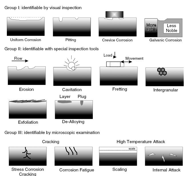
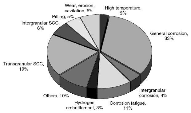
Failure statistics of large chemical process plant in Germany
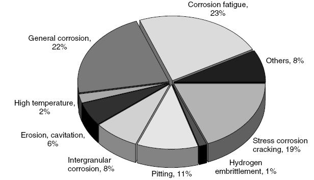
Failure statistics of large chemical process in the United States
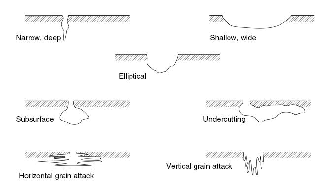
Pitting types
A form of corrosion that can occur at the junction of dissimilar metals when they are joined together in a suitable electrolyte, such as a moist or aqueous environment, or soils containing moisture. Affected materials are all metals with the exception of most noble metals.
For galvanic corrosion, three conditions must be met:
i) Presence of an electrolyte, a fluid that can conduct a current. Moisture or a separate water phase is usually required for the solution to have enough conductivity.
ii) Two different materials or alloys known as the anode and the cathode, in contact with an electrolyte.
iii) An electrical connection must exist between the anode and the cathode.
The more noble mateiral (cathode) is protected by sacrificial corrosion of the more active material (anode). The anode corrodes at a higher rate than it would if it were not connected to the cathode. The relative exposed surface areas between anodic material and the cathodic material has a significant effect:
i) Corrosion rates of the anode can be high, if there is a small anode to cathode ratio.
ii) Corrosion rates of the anode will be less affected if there is a large anode to cathode ratio.
iii) If there is a galvanic couple, the more noble material may need to be coated. If the active material were coated, a large cathode to anode area can accelerate corrosion of the anode at any breaks in the coating.
iv) The same alloy may act as both an anode and a cathode due to surface films, scale, and/or local environment (for example, old steel pipe connected to new steel pipe).
Affected Units or Equipment
Galvanic corrosion can occur in any unit where there is a conductive fluid and alloys are coupled. Heat exchangers are susceptible if the tube material is different from the tubesheet and/or baffles, particularly if salt water cooling is utilized. Buried pipelines, electrical transmission support towers and ship hulls are typical locations for galvanic corrosion.
Appearance or Morphology of Damage
Damage occurs where two materials are joined at welded or bolted connections. The more active material can suffer generalized loss in thickness or may have the appearance of a crevice, groove or pitting corrosion, depending on the driving force, conductivity and relative anodic/cathodic areas ratio.
Corrosion of the anode may be significantly higher immediately adjacent to the connection to the cathode, depending on solution conductivity.
Preferential galvanic corrosion of the more active component of the two materials.
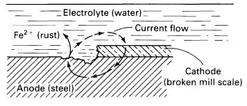
Schematic showing how breaks in mill scale (Fe3O4) can lead to galvanic corrosion of steel
Galvanic corrosion of a carbon steel nipple in a SS vessel in warm water service
A form of corrosion that occurs from moisture associated with atmospheric conditions. Marine environments and moist polluted industrial environments with airborne contaminants are most severe. Dry rural environments cause very little corrosion. Affected materials are carbon steel, low alloy steels and copper alloyed aluminum. Many authors classify atmospheric corrosion under categories of dry, damp, and wet, thus emphasizing the different mechanisms of attack under increasing humidity or moisture.
Damp corrosion requires moisture in the atmosphere and increases in aggressiveness with the moisture content. When the humidity exceeds a critical value, which is around 70% relative humidity, an invisible thin film of moisture will form on the surface of the metal, providing an electrolyte for current transfer. The critical value depends on surface conditions such as cleanliness, corrosion product buildup, or the presence of salts or other contaminants that are hygroscopic and can absorb water at lower relative humidities.
Wet corrosion occurs when water pockets or visible water layers are formed on the metal surfaces because of sea spray, rain, or drops of dew. Crevices or condensation traps also promote the pooling of water and lead to wet atmospheric corrosion even when the flat surfaces of a metal component appear to be dry.
Critical factors include the physical location (industrial, marine, rural); moisture (humidity), particularly designs that trap moisture or when present in a cooling tower mist; temperature; presence of salts, sulfur compounds and dirt. Marine environments can be very corrosive (20 mpy) as are industrial environments that contain acids or sulfur compounds that can form acids (5-10 mpy). Inland locations exposed to a moderate amount of precipitation or humidity are considered moderately corrosive environments (~1-3 mpy). Dry rural environments usually have very low corrosion rates (<1 mpy). Designs that trap water or moisture in crevices are more prone to attack. Corrosion rates increase with temperature up to about 120°C. Above this temperatre, surfaces are usually too dry for corrosion to occur except under insulation.
Chlorides, H2S, fly ash and other airborne contaminates from cooling tower drift, furnace stacks and other equipment accelerate corrosion. Bird turds can also cause accelerated corrosion and unsightly stains.
Affected Units or Equipment
Piping and equipment with operating temperatures sufficiently low to allow moisture to be present. A paint or coating system in poor condition. Equipment may be susceptible if cycled between ambient and higher or lower operating temperatures. Equipment shut down or idled for prolonged periods unless properly mothballed. Tanks and piping are particularly susceptible. Piping that rests on pipe supports is very prone to attack due to water entrapment between the pipe and the support. Orientation to the prevailing wind and rain can also be a factor. Piers and docks are very prone to attack. Bimetallic connections such as copper to aluminum electrical connections
Appearance
The attack will be general or localized, depending upon whether or not the moisture is trapped. If there is no coating or if there is a coating failure, corrosion or loss in thickness can be general. Localized coating failures will tend to promote corrosion. Metal loss may not be visually evident, although normally a distinctive iron oxide (red rust) scale forms.
Prevention / Mitigation
Surface preparation and proper coating application are critical for long-term protection in corrosive environments.
Inspection and Monitoring
VT and UT are techniques that can be used.
Relative corrosivity of atmospheres at different locations
|
Location
|
Type of atmosphere
|
Average weight loss of iron specimens in 1 year, mg/cm2
|
Relative corrosivity
|
|
Khartoum, Sudan
|
Dry island (arid)
|
0.08
|
1
|
|
Singapore
|
Tropical/marine
|
0.69
|
9
|
|
State College, PA
|
Rural
|
1.90
|
25
|
|
Panama Canal Zone
|
Tropical/marine
|
2.28
|
31
|
|
Kure Beach, NC (250-m, or 800-ft, lot)
|
Marine
|
2.93
|
38
|
|
Kearny, NJ
|
Industrial
|
3.92
|
52
|
|
Pittsburgh, PA
|
Industrial
|
4.88
|
65
|
|
Frodingham, UK
|
Industrial
|
7.50
|
100
|
|
Daytona Beach, FL
|
Marine
|
10.34
|
138
|
|
Kure Beach, NC (25-m, or 80-ft, lot)
|
Marine
|
35.68
|
475
|
External corrosion on lower vessel shell and nozzle attachment weld
Corrosion Under Insulation (CUI) is a corrosion of piping, pressure vessels and structural components resulting from water trapped under insulation or fireproofing. It affects carbon steel, low alloy steels, 300 Series SS and duplex stainless steels.
Design of insulation system, insulation type, temperature, environment (humidity, rainfall and chlorides from marine environment, industrial environments containing high SO2) are critical factors. Poor design and/or installations that allow water to become trapped will increase CUI. Corrosion rates increase with increasing metal temperature up to the point where the water evaporates quickly. Corrosion becomes more severe at metal temperatures between the boiling point 100°C and 120°C, where water is less likely to vaporize and insulation stays wet longer. In marine environments or areas where significant amounts of moisture may be present, the upper temperature range where CUI may occur can be extended significantly above 120°C. Insulating materials that hold moisture (wick) can be more of a problem. Cyclic thermal operation or intermittent service can increase corrosion. Equipment that operates below the water dewpoint tends to condense water on the metal surface thus providing a wet environment and increasing the risk of corrosion. Damage is aggravated by contaminants that may be leached out of the insulation, such as chlorides. Plants located in areas with high annual rainfall or warmer, marine locations are more prone to CUI than plants located in cooler, drier, mid-continent locations. Environments that provide airborne contaminants such as chlorides (marine environments, cooling tower drift) or SO2 (stack emissions) can accelerate corrosion.
Affected Units or Equipment
Carbon and low alloy steels are subject to pitting and loss in thickness. 300 Series SS, 400 Series SS and duplex SS are subject to pitting and localized corrosion. 300 Series SS are also subject to Stress Corrosion Cracking (SCC) if chlorides are present, while the duplex SS are less susceptible.
Affected Units or Equipment
Location Issues
Common areas of concern in process units are higher moisture areas such as those areas down-wind from cooling towers, near steam vents, deluge systems, acid vapors, or near supplemental cooling with water spray.
Design Issues
CUI can be found on equipment with damaged insulation, vapor barriers, weatherproofing or mastic, or protrusions through the insulation or at insulation termination points such as flanges. Equipment designed with insulation support rings welded directly to the vessel wall (no standoff); particularly around ladder and platform clips, and lifting lugs, nozzles and stiffener rings. Piping or equipment with damaged/leaking steam tracing. Localized damage at paint and/or coating systems.
Locations where moisture/water will naturally collect (gravity drainage) before evaporating (insulation support rings on vertical equipment) and improperly terminated fireproofing. The first few feet of a horizontal pipe run adjacent to the bottom of a vertical run is a typical a CUI location.
Appearance or Morphology of Damage
After insulation is removed from carbon and low alloy steels, CUI damage often appears as loose, flaky scale covering the corroded component. Damage may be highly localized. In some localized cases, the corrosion can appear to be carbuncle type pitting (usually found under a failed paint/coating system). For 300 Series SS, specifically in older calcium silicate insulation (known to contain chlorides), localized pitting and chloride stress corrosion cracking can occur.
Prevention / Mitigation
Since the majority of construction materials used in plants are susceptible to CUI degradation, mitigation is best achieved by using appropriate paints/coatings and maintaining the insulation/sealing/vapor barriers to prevent moisture ingress. High quality coatings, properly applied, can provide long term protection. Careful selection of insulating materials is important. Closed-cell foam glass materials will hold less water against the vessel/pipe wall than mineral wool and potentially be less corrosive. Low chloride insulation should be used on 300 Series SS to minimize the potential for pitting and chloride SCC. It is not usually possible to modify operating conditions. However, consideration should be given to removing the insulation on equipment where heat conservation is not as important. An inspection plan for corrosion under insulation should be a structured and systematic approach starting with prediction/analysis, then looking at the more invasive procedures. The inspection plan should consider operating temperature; type and age/condition of coating; and type and age/condition of insulation material. Additional prioritization can be added from a physical inspection of the equipment, looking for evidence of insulation, mastic and/or sealant damage, signs of water penetration and rust in gravity drain areas around the equipment.
Utilize multiple inspection techniques to produce the most cost effective approach, including:
i) Partial and/or full stripping of insulation for visual examination.
ii) UT for thickness verification.
iii) Real-time profile x-ray (for small bore piping).
iv) Neutron backscatter techniques for identifying wet insulation.
v) Deep penetrating eddy-current inspection (can be automated with a robotic crawler).
vi) IR thermography looking for wet insulation and/or damaged and missing insulation under the jacket.
vii) Guided wave UT.
44 CUI on bottom of heat exchanger
General or localized corrosion of carbon steels and other metals caused by dissolved salts, gases, organic compounds or microbiological activity. Carbon steel, all grades of stainless steel, copper, aluminum, titanium and nickel base alloys are affected.
Cooling water corrosion and fouling are closely related and should be considered together. Fluid temperature, type of water (fresh, brackish, salt water) and the type of cooling system (once-through, open circulating, closed circulating), oxygen content, and fluid velocities are critical factors. Increasing cooling water outlet temperatures and or process side inlet temperatures tend to increase corrosion rates as well as fouling tendency. Increasing oxygen content tends to increase carbon steel corrosion rates. If the process side temperature is above 140oF (60oC), a scaling potential exists with fresh water and becomes more likely as process temperatures increase and as cooling water inlet temperatures rise. Brackish and salt water outlet temperatures above about 50°C may cause serious scaling.
Fouling may occur from mineral deposits (hardness), silt, suspended organic materials, corrosion products, mill scale, marine and microbiological growth. Velocities should be high enough to minimize fouling and drop out of deposits but not so high as to cause erosion. Velocity limits depend on the tube material and water quality. Low velocities can promote increased corrosion. Velocities below about 3 fps (1 m/s) are likely to result in fouling, sedimentation and increased corrosion in fresh and brackish water systems. Accelerated corrosion can also result from dead spots or stagnant areas if cooling water is used on the shell side of condensers/coolers rather than the preferred tube side. 300 Series SS can suffer pitting corrosion, crevice corrosion and SCC in fresh, brackish and salt water systems.
Copper/zinc alloys can suffer dezincification in fresh, brackish and salt water systems. The copper/zinc alloys can suffer SCC if any ammonia or ammonium compounds are present in the water or on the process side. ERW carbon steel may suffer severe weld and/or heated affected zone corrosion in fresh and/or brackish water.
When connected to a more anodic material, titanium may suffer severe hydriding embrittlement. Generally, the problem occurs at temperatures above 180oF (82oC) but can occur at lower temperatures.
Affected Units or Equipment
Cooling water corrosion is a concern with water-cooled heat exchangers and cooling towers in all applications across all industries.
Appearance or Morphology of Damage
Cooling water corrosion can result in many different forms of damage including general corrosion, pitting corrosion, MIC, stress corrosion cracking and fouling. General or uniform corrosion of carbon steel occurs when dissolved oxygen is present. Localized corrosion may result from underdeposit corrosion, crevice corrosion or microbiological corrosion. Deposits or crevices can lead to underdeposit or crevice corrosion of any of the affected materials. Wavy or smooth corrosion at nozzle inlets/outlets and tube inlets may be due to flow induced corrosion, erosion or abrasion. Corrosion at ERW weld areas will appear as grooving along the weld fusion lines. Metallurgical analysis of tube samples may be required to confirm the mode of failure.
Prevention / Mitigation
Cooling water corrosion (and fouling) can be prevented by proper design, operation and chemical treatment of cooling water systems. Design for process side inlet temperatures below 60°C. Minimum and maximum water velocities must be maintained, particularly in salt water systems. The metallurgy of heat exchanger components may need to be upgraded for improved resistance, especially in waters with high chloride content, low velocity, high process temperatures, and/or poorly maintained water chemistry. Periodic mechanical cleaning of tube ID’s and OD’s should be performed in order to maintain clean heat transfer surfaces. With very few exceptions, cooling water should be on the tube side to minimize stagnant areas.
Inspection and Monitoring
Cooling water should be monitored for variables that affect corrosion and fouling including, pH, oxygen content, cycles of concentration, biocide residual, biological activity, cooling water outlet temperatures, hydrocarbon contamination and process leaks. Periodic calculation of U-factors (heat exchanger performance measurement) will provide information on scaling and fouling. Ultrasonic flow meters can be used to check the velocity of water in the tubes. EC or IRIS inspection of tubes. Splitting representative tubes.
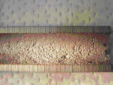
Cooling water corrosion of a CS heat exchanger tube operating at 30°C
General corrosion and pitting in the boiler system and condensate return piping. Affected materials are primarily carbon steel, some low alloy steel, some 300 Series SS and copper based alloys.
Corrosion in boiler feedwater and condensate return systems is usually the result of dissolved gases, oxygen and carbon dioxide. Critical factors are the concentration of dissolved gas (oxygen and carbon dioxide), pH, temperature, quality of the feedwater and the specific feedwater treating system. Corrosion protection in the boiler is accomplished by laying down and continuously maintaining a layer of protective Fe3O4 (magnetite). d) The chemical treatment for scale and deposit control must be adjusted to coordinate with the oxygen scavenger for the specific water service and boiler feedwater treating system. Ammonia SCC of Cu-Zn alloys can occur due to hydrazine, neutralizing amines or ammoniacal compounds.
Affected Units or Equipment
Corrosion can occur in the external treatment system, deaerating equipment, feedwater lines, pumps, stage heaters and economizers as well as the steam generation system on both the water and fire sides and the condensate return system.
Appearance or Morphology of Damage
Corrosion from oxygen tends to be a pitting type damage and can show up anywhere in the system even if only very small quantities break through the scavenging treatment. Oxygen is particularly aggressive in equipment such as closed heaters and economizers where there is a rapid water temperature rise. Corrosion in the condensate return system tends to be due to carbon dioxide although some oxygen pitting problems can occur if the oxygen scavenging treatment is not working correctly. Carbon dioxide corrosion tends to be a smooth grooving of the pipe wall.
Prevention/Mitigation
Oxygen scavenging treatments typically include catalyzed sodium sulfite or hydrazine depending on the system pressure level along with proper mechanical deareator operation. A residual of the oxygen scavenger is carried into the steam generation system to handle any oxygen ingress past the deaerator. If the scale/deposit control/magnetite maintenance treatment scheme does not minimize carbon dioxide in the condensate return system, an amine inhibitor treatment might be required.
Inspection and Monitoring
Water analysis is the common monitoring tool used to assure that the various treatment systems are performing in a satisfactory manner. Parameters which can be monitored for signs of upset include the pH, conductivity, chlorine or residual biocide, and total dissolved solids to check for leaks in the form of organic compounds. There are no proactive inspection methods other than developing an appropriate program when problems such as a ruptured boiler tube or condensate leaks are recognized in the various parts of complex boiler water and condensate systems. Deaerator cracking problems can be evaluated off-line at shutdowns by utilizing properly applied wet fluorescence magnetic particle inspection.
Carbon dioxide (CO2) corrosion results when CO2 dissolves in water to form carbonic acid (H2CO3). The acid may lower the pH and sufficient quantities may promote general corrosion and/or pitting corrosion of carbon steel. Affected materials are carbon steel and low alloy steels.
The partial pressure of CO2, pH and temperature are critical factors. Increasing partial pressures of CO2 result in lower pH condensate and higher rates of corrosion. Corrosion occurs in the liquid phase, often at locations where CO2 condenses from the vapor phase. Increasing temperatures increase corrosion rate up to the point where CO2 is vaporized. Increasing the level of chromium in steels offers no major improvement in resistance until a minimum of 12% is reached.
Affected Units or Equipment
Boiler feedwater and condensate systems in all units are affected. Effluent gas streams of the shift converters in hydrogen plants can be affected. Corrosion usually occurs when the effluent stream drops below the dew point, approximately 150°C. Corrosion rates as high as 1000 mpy have been observed. Overhead systems of regenerators in CO2 removal plants are affected.
Appearance or Morphology of Damage
Localized thinning and/or pitting corrosion of carbon steel. Carbon steel may suffer deep pitting and grooving in areas of turbulence. Corrosion generally occurs in areas of turbulence and impingement and sometimes at the root of piping welds.
Prevention / Mitigation
Corrosion inhibitors can reduce corrosion in steam condensate systems. Vapor phase inhibitors may be required to protect against condensing vapors. Increasing condensate pH above 6 can reduce corrosion in steam condensate systems. The 300 Series SS are highly resistant to corrosion in most applications. Selective upgrading to stainless steels is usually required in operating units designed to produce and/or remove CO2 (such as hydrogen plants and CO2 removal units). Steam condensate systems that experience CO2 problems are usually the result of operating problems. 400 Series SS and duplex SS are also resistant.
Inspection and Monitoring
VT, UT and RT inspection techniques should focus on general and local loss in thickness where water wetting is anticipated. Preferential corrosion of weld seams may require angle probe UT or RT.
Corrosion may occur along the bottom surface of the pipe if there is a separate water phase, at the top surface of the pipe if condensation in wet gas systems is anticipated, and in the turbulent flow areas at elbow and tees. Monitor water analyses (pH, Fe, etc.) to determine changes in operating conditions.
CO2 Corrosion pitting of a Carbon steel production flow line
Sulfur and chlorine species in fuel will form sulfur dioxide, sulfur trioxide and hydrogen chloride within the combustion products. At low enough temperatures, these gases and the water vapor in the flue gas will condense to form sulfurous acid, sulfuric acid and hydrochloric acid which can lead to severe corrosion. Affected materials are carbon steel, low alloy steels and 300 Series SS.
The concentration of contaminants (sulfur and chlorides) in the fuel and the operating temperature of flue gas metal surfaces determine the likelihood and severity of corrosion. Since all fuels contain some amount of sulfur, sulfuric and sulfurous acid dewpoint corrosion can occur if the metal temperatures are below the dewpoint. The dewpoint of sulfuric acid depends on the concentration of sulfur trioxide in the flue gas, but is typically about 140°C. Similarly, the dewpoint of hydrochloric acid depends on the concentration of hydrogen chloride. It is typically about 55°C.
Affected Units or Equipment
All fired process heaters and boilers that burn fuels containing sulfur have the potential for sulfuric acid dewpoint corrosion in the economizer sections and in the stacks. Heat-Recovery Steam Generators (HRSG’s) that have 300 Series SS feedwater heaters may suffer chloride-induced stress corrosion cracking from the gas side (OD) when the temperature of the inlet water is below the dewpoint of hydrochloric acid. 300 Series SS feedwater heaters in HRSG’s are potentially at risk if the atmosphere of the combustion turbine includes chlorine. Cooling tower drift from cooling towers that use chlorine-based biocides may blow into the combustion turbine and lead to potential damage in the feedwater heaters.
Appearance or Morphology of Damage
Sulfuric acid corrosion on economizers or other carbon steel or low alloy steel components will have general wastage often with broad, shallow pits, depending on the way the sulfuric acid condenses. For the 300 Series SS feedwater heaters in HRSG’s, stress corrosion cracking will have surface breaking cracks and the general appearance will be somewhat crazed.
Prevention / Mitigation
Maintain the metallic surfaces at the back end of the boilers and fired heaters above the temperature of sulfuric acid dewpoint corrosion. For HRSG’s, avoid the use of 300 Series SS in the feedwater heaters if the environment is likely to contain chlorides. Similar damage occurs in oil-fired boilers when the units are water-washed to remove ash if the final rinse does not neutralize the acid salts. Sodium carbonate should be added to the final rinse as a basic solution to neutralize the acidic ash constituents.
Inspection and Monitoring
Wall-thickness measurements by UT methods will monitor the wastage in economizer tubes. Stress corrosion cracking of 300 Series SS can be found using VT and PT inspection.
A form of corrosion caused by living organisms such as bacteria, algae or fungi. It is often associated with the presence of tubercles or slimy organic substances. Most common materials of construction including carbon and low alloy steels, 300 Series SS and 400 Series SS, aluminum, copper and some nickel base alloys.
MIC is usually found in aqueous environments or services where water is always or sometimes present, especially where stagnant or low-flow conditions allow and/or promote the growth of microorganisms. Because there are several types, organisms can survive and grow under severe conditions including lack of oxygen, light or dark, high salinity, pH range of 0 to 12, and temperatures from -20°C to 110°C. Systems may become “inoculated” by the introduction of organisms that multiply and spread unless controlled. Different organisms thrive on different nutrients including inorganic substances (e.g., sulfur, ammonia, H2S) and inorganic substances (e.g., hydrocarbons, organic acids). In addition, all organisms require a source of carbon, nitrogen and phosphorous for growth. In-leakage of process contaminants such as hydrocarbons or H2S may lead to a massive increase in biofouling and corrosion.
Affected Units or Equipment
MIC is most often found in heat exchangers, bottom water of storage tanks, piping with stagnant or low flow, and piping in contact with some soils. MIC is also found in equipment where the hydrotest water has not been removed or equipment has been left outside and unprotected. Product storage tanks and water cooled heat exchangers in any unit where cooling water is not properly treated can be affected. Fire water systems can be affected.
Appearance or Morphology of Damage
MIC corrosion is usually observed as localized pitting under deposits or tubercles that shield the organisms. Damage is often characterized by cup-shaped pits within pits in carbon steel or subsurface cavities in stainless steel.
Prevention / Mitigation
Microbes require water to thrive. Systems that contain water (cooling water, storage tanks, etc.) should be treated with biocides such as chlorine, bromine, ozone, ultraviolet light or proprietary compounds. Proper application of biocides will control but not eliminate microbes so that continued treatment is necessary. Maintain flow velocities above minimum levels. Minimize low flow or stagnant zones. Systems that are not designed or intended for water containment should be kept clean and dry. Empty hydrotest water as soon as possible. Blow dry and prevent moisture intrusion. Wrapping and cathodically protecting underground structures have been effective in preventing MIC. Effective mitigation of established organisms requires complete removal of deposits and organisms using a combination of pigging, blasting, chemical cleaning and biocide treatment. Add biocides to water phase in storage tanks. Maintain coatings on the interior of storage tanks.
Inspection and Monitoring
In cooling water systems, effectiveness of treatment is monitored by measuring biocide residual, microbe counts and visual appearance. Special probes have been designed to monitor for evidence of fouling which may precede or coincide with MIC damage. An increase in the loss of duty of a heat exchanger may be indicative of fouling and potential MIC damage. Foul smelling water may be a sign of trouble.
Bacteria on metal surface
Diagram of ideal biofilm showing relationship of aerobic and anaerobic sessile bacteria, with incipient pit at bottom
Type 304 stainless steel exchanger tubes failed from pitting corrosion on the shell side in cooling water service after 2.5 years without biocide treatment.
The deterioration of metals exposed to soils is referred to as soil corrosion. Affected materials are carbon steel, cast iron and ductile iron.
The severity of soil corrosion is determined by many factors including operating temperature, moisture and oxygen availability, soil resistivity (soil condition and characteristics), soil type (water drainage), and homogeneity (variation in soil type), cathodic protection, stray current drainage, coating type, age, and condition. There is no single parameter that can be used to determine soil corrosivity. Instead, a number of characteristics must be combined to estimate the corrosion in particular soil as outlined in ASTM STP 741 as well as API RP 580 and Publ 581.
Soil resistivity is frequently used to estimate soil corrosivity, mainly because it is easy to measure. Soil resistivity is related to soil moisture content and dissolved electrolytes in the soil water. Soils having high moisture content, high dissolved salt concentrations, and high acidity are usually the most corrosive. Soil-to-air interface areas are often much more susceptible to corrosion than the rest of the structure because of moisture and oxygen availability. Corrosion rates increase with increasing metal temperature. Other factors that affect soil corrosion include galvanic corrosion, dissimilar soils, stray currents, differential aeration corrosion cells, and microbiologically induced corrosion.
Affected Units or Equipment
Underground piping and equipment as well as buried tanks and the bottoms of above ground storage tanks, ground supported metal structures
Appearance or Morphology of Damage
Soil corrosion appears as external thinning with localized losses due to pitting. The severity of corrosion depends on the local soil conditions and changes in the immediate environment along the equipment metal surface.Poor condition of a protective coating is a tell tale sign of potential corrosion damage.
Prevention / Mitigation
Soil corrosion of carbon steel can be minimized through the use of special backfill, coatings and cathodic protection. The most effective protection is a combination of a corrosion resistant coating and a cathodic protection system.
Inspection and Monitoring
The most common method used for monitoring underground structures is measuring the structure to soil potential using dedicated reference electrodes near the structure (corrected for IR drop error). Cathodic protection should be performed and monitored in accordance with NACE RP 0169. There are many techniques for inspecting buried or on-grade metallic omponents. Piping may be inspected by inline inspection devices, guided ultrasonic thickness tools, indirectly by pressure testing, or visually by evaluation. The same or similar techniques may be used on other structures.
Corrosion of carbon steel pipe at the soil-air interface where the pipe emerges from underground.
Localized corrosion due to the concentration of caustic or alkaline salts that usually occurs under evaporative or high heat transfer conditions. However, general corrosion can also occur depending on alkali or caustic solution strength. Affected materials are primarily carbon steel, low alloy steels and 300 Series SS.
Major contributing factors are the presence of caustic (NaOH or KOH). The following are sources of caustic:
a) Caustic is sometimes added to process streams for neutralization or as a reactant.
b) It is sometimes intentionally added to boiler feedwater at low concentrations or may enter inadvertently during regeneration of demineralizers.
c) Alkaline salts may also enter process streams through leaks in condensers or process equipment.
d) Some process units utilize caustic solutions for neutralizing or removal of sulfur compounds.
e) A concentrating mechanism must exist to build up the caustic strength.
f) Caustic may become concentrated by departure from DNB, evaporation and deposition.
Affected Units or Equipment
Caustic corrosion is most often associated with boilers and steam generating equipment including heat exchangers. Similar concentrating effects of caustic may occur where caustic is added to crude unit charge. Accelerated localized corrosion can occur in preheat exchangers, furnace tubes and transfer lines, unless the caustic is effectively mixed in the oil stream. Units that use caustic for removing sulfur compounds from product streams.
Appearance or Morphology of Damage
Typically characterized by localized metal loss which may appear as grooves in a boiler tube or locally thinned areas under insulating deposits. Deposits may fill corroded depressions and mask damage below. Probing suspect areas with a sharp instrument may be required. Localized gouging may result along a waterline where corrosives concentrate. In vertical tubes, this may appear as a circumferential groove. In horizontal or sloped tubes, grooving may appear at the top of the tube or as longitudinal grooves on opposite sides of the tube. Exposure to high solution strength caustic can result in general corrosion of carbon steel above 80°C and very high corrosion rates above 100°C.
Prevention / Mitigation
In steam generating equipment, caustic corrosion is best prevented through proper design. Damage can be minimized by reducing the amount of free caustic, by ensuring adequate water flooding and water flow, by ensuring proper burner management to minimize hot spots on heater tubes, and by minimizing the ingress of alkaline producing salts into condensers. In process equipment, caustic injection facilities should be designed to allow proper mixing and dilution of caustic in order to avoid the concentration of caustic on hot metal surfaces. Carbon steel and 300 Series SS have serious corrosion problems in high strength caustic solutions above about 65°C. Alloy 400 and some other nickel base alloys exhibit much lower corrosion rates.
Inspection and Monitoring
For process equipment, UT thickness gauging is useful to detect and monitor general corrosion due to caustic. However, localized losses due to caustic corrosion may be difficult to locate. Injection points should be inspected in accordance with API 570. UT scans and radiography can be used. Steam generation equipment may require visual inspection with the use a boroscope.
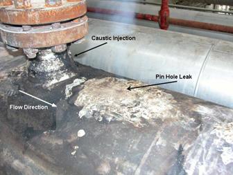
Location of the Leak Downstream of the Caustic Injection Point
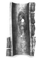
Caustic corrosion of boiler tubes
Dealloying is a selective corrosion mechanism in which one or more constituents of an alloy are preferentially attacked leaving a lower density (dealloyed) often porous structure. Component failure may occur suddenly and unexpectedly because mechanical properties of the dealloyed material are significantly degraded. Affected materials are primarily copper alloys (brass, bronze, tin) as well as Alloy 400 and cast iron.
Factors which influence dealloying include the composition of the alloy and exposure conditions including temperature, degree of aeration, pH and exposure time. Dealloying occurs with several different alloys but is usually limited to very specific alloy-environment combinations. Exact conditions under which dealloying occurs are often hard to define and damage may occur progressively over many years in service. Common examples of where dealloying has been found.
Affected Units or Equipment
Underground cast iron piping when exposed to certain soils. In cooling water applications, heat exchanger tubing (brass, Al brass) is susceptible to dealloying in some brackish and seawater applications but often the tubesheets suffer significant damage. Problems may also occur in some fresh or domestic water systems. Boiler feedwater piping systems and afterboiler components may suffer dealloying including bronze pumps, Monel strainers and brass pressure gage fittings.
Appearance or Morphology of Damage
There is often a significant color change or a deep etched (corroded) appearance as one element is removed from the alloy. However, depending on the alloy, the outward appearance of the affected material may not be noticeable upon visual inspection, even where the full wall thickness is degraded. Attack may be uniform through the cross-section (layer-type) or it can be localized (plug-type). In some cases, the original material is completely dealloyed yet the component exhibits virtually no dimensional or other visible changes.
Prevention / Mitigation
It is often difficult to predict whether conditions will be conducive to dealloying in a particular environment or service, so that one must be cognizant of the susceptibility of certain alloys, and the possible resulting consequences. Resistance to dealloying can sometimes be improved by the addition of certain alloying elements so that a similar alloy with a different composition may be resistant. For example, tin tends to inhibit dealloying of copper alloys; admiralty brass is inhibited by the addition of a very small amount of phosphorous, antimony or arsenic; and dealuminification of aluminum-bronze can be prevented by heat treatment to produce an α and β microstructure. Continued degradation of a dealloyed component can only be prevented by altering the exposure conditions or replacing it with a resistant material. Depending on the alloy-environment combination, cathodic protection or barrier coatings may be effective.
Inspection and Monitoring
Many alloys change color in the affected area, however, scale removal may be required to determine the depth of attack. Dealloying in brasses is visually evident by a reddish, copper color instead of the yellow brass color. Graphitic corrosion turns cast iron charcoal gray and the material can be cut or gouged with a knife. Metallographic examination may be required to confirm the extent of damage. A significant reduction in hardness may accompany dealloying, although affected areas may be localized. Acoustic techniques (loss of “metallic ring”) and ultrasonic attenuation are applicable, but UT thickness measurements are not. Fitness-For-Service (FFS) analysis of dealloyed components should consider that the dealloyed portion may be brittle and contribute little or no mechanical strength or load bearing capability.
Cross section of a silicon-brass alloy C87500 pump impeller from stagnant fire-water service. Layer-type dezincification depleted the zinc and left this porous red color of the copper.
Graphitic Corrosion
Cast irons are comprised of graphite particles embedded in an iron matrix. Graphitic corrosion is a form of dealloying in which the iron matrix is corroded, leaving corrosion products and porous graphite. Attack results in a porous structure with a loss of strength, ductility and density. It usually occurs under low pH and stagnant conditions, especially in contact with soils or waters high in sulfates. Affected materials are primarily gray cast iron, but also nodular and malleable cast irons experience graphitic corrosion. However, nodular and malleable cast irons tend to crumble when attacked. White iron is not subject to this damage because there is no free graphite.
Graphitic corrosion occurs with several different cast iron alloys but is usually limited to very specific microstructure-environment combinations. Factors that influence graphitic corrosion include the composition of the alloy and exposure conditions including temperature, degree of aeration, pH and exposure time. Damage occurs in the presence of moisture or an aqueous phase, usually below 90°C. Damage may take many months or years to progress but can increase in severity if the pH drops. Much of the damage occurs during stagnant conditions when high concentrations of sulfates are present. Graphite is cathodic to the iron matrix. The iron matrix preferentially corrodes and cathodically protects the graphite in certain conductive waters or soils. Graphitic corrosion may affect adjacent components by causing galvanic corrosion.
Affected Units or Equipment
Graphitic corrosion can occur in soft water, salt water, mine waters, dilute acids and in underground piping as well as in boiler feedwater equipment. Typical examples include feedwater piping, pumps (including pump impellers), valves, and underground cast iron pipe. Fire water systems are particularly vulnerable.
Appearance or Morphology of Damage
Damage may be widespread or it may also occur in localized areas in which the majority of the component is unaffected. The damage may not be noticeable upon visual inspection even where the full wall thickness is degraded. Damaged areas will be soft and easily gouged with a knife or hand tool. Metallographic examination may be required to confirm the extent of damage.
Inspection and Monitoring
UT is not a good method for detecting damage. Acoustic techniques (loss of “metallic ring”) and ultrasonic attenuation are applicable. A significant reduction in hardness may accompany dealloying, although affected areas may be localized.
Prevention / Mitigation
It is often difficult to predict if exposure conditions will cause this form of dealloying in a particular environment or service. One must be aware of the potential susceptibility of cast irons. Internal graphitic corrosion can be prevented by coatings and/or cement linings. External graphitic corrosion can be prevented by external coatings or cathodic protection in severely corrosive soils.
Graphitic Corrosion- gray iron pipe that failed because of graphitic corrosion
High temperature corrosion
Oxygen reacts with carbon steel and other alloys at high temperature converting the metal to oxide scale. It is most often present as oxygen in the surrounding air (approximately 20%) used for combustion in fired heaters and boilers. Affected materials are all iron based materials including carbon steel and low alloy steels, both cast and wrought, as well as all 300 Series SS, 400 Series SS and nickel base alloys also oxidize to varying degrees, depending on composition and temperature.
The primary factors affecting high temperature oxidation are metal temperature and alloy composition. Oxidation of carbon steel begins to become significant above about 540°C. Rates of metal loss increase with increasing temperature. In general, the resistance of carbon steel and other alloys is determined by the chromium content of the material. Increasing chromium levels produce a more protective oxide scale. The 300 Series SS are resistant to scaling up to about 820°C.
Affected Units or Equipment
Oxidation occurs in fired heaters and boilers as well as other combustion equipment, piping and equipment that operates in high temperature environments when metal temperatures exceed about 540°C.
Appearance or Morphology of Damage
Most alloys, including carbon steels and low alloy steels, suffer general thinning due to oxidation. Usually, the component will be covered on the outside surface with an oxide scale, depending on the temperature and exposure time. 300 Series SS and nickel alloys generally have a very thin dark scale unless exposed to extremely high temperatures where metal loss rates are excessive.
Prevention / Mitigation
Resistance to oxidation is best achieved by upgrading to a more resistant alloy. Chromium is the primary alloying element that affects resistance to oxidation. Other alloying elements, including silicon and aluminum, are effective but their concentrations are limited due to adverse affects on mechanical properties. They are often used in special alloys for applications such as heater supports, burner tips and components for combustion equipment.
Inspection and Monitoring
Process conditions should be monitored for establishing trends of high temperature equipment where oxidation can occur. Temperatures can be monitored through the use of tubeskin thermocouples and/or infrared thermography. Loss in thickness due to oxidation is usually measured using external ultrasonic thickness measurements
Corrosion of carbon steel and other alloys resulting from their reaction with sulfur compounds in high temperature environments. The presence of hydrogen accelerates corrosion. Affected materials are all iron based materials including carbon steel and low alloy steels, 300 Series SS and 400 Series SS. Nickel base alloys are also affected to varying degrees depending on composition, especially chromium content. Copper base alloys form sulfide at lower temperatures than carbon steel.
Major factors affecting sulfidation are alloy composition, temperature and concentration of corrosive sulfur compounds. Susceptibility of an alloy to sulfidation is determined by its ability to form protective sulfide scales. Sulfidation of iron-based alloys usually begins at metal temperatures above 250°C. The typical effects are increasing temperature, chromium content and sulfur content on metal loss. In general, the resistance of iron and nickel base alloys is determined by the chromium content of the material. Increasing the chromium content significantly increases resistance to sulfidation. 300 Series SS, such as Types 304, 316, 321 and 347, are highly resistant in most refining process environments. Nickel base alloys are similar to stainless steels in that similar levels of chromium provide similar resistance to sulfidation. Crude oils, coal and other hydrocarbon streams contain sulfur at various concentrations. Total sulfur content is made up of many different sulfur-containing compounds. Sulfidation is primarily caused by H2S and other reactive sulfur species as a result of the thermal decomposition of sulfur compounds at high temperatures. Some sulfur compounds react more readily to form H2S. Therefore, it can be misleading to predict corrosion rates based on weight percent sulfur alone. A sulfide scale on the surface of the component offers varying degrees of protection depending on the alloy and the severity of the process stream.
Affected Units or Equipment
Sulfidation occurs in piping and equipment in high temperature environments where sulfur-containing streams are processed. Common areas of concern are the crude, FCC, coker, vacuum, visbreaker and hydroprocessing units. Heaters fired with oil, gas, coke and most other sources of fuel may be affected depending on sulfur levels in the fuel. Boilers and high temperature equipment exposed to sulfur-containing gases can be affected.
Appearance or Morphology of Damage
Depending on service conditions, corrosion is most often in the form of uniform thinning but can also occur as localized corrosion or high velocity erosion-corrosion damage. A sulfide scale will usually cover the surface of components. Deposits may be thick or thin depending on the alloy, corrosiveness of the stream, fluid velocities and presence of contaminants.
Prevention / Mitigation
Resistance to sulfidation is generally achieved by upgrading to a higher chromium alloy. Piping and equipment constructed from solid or clad 300 Series SS or 400 Series SS can provide significant resistance to corrosion. Aluminum diffusion treatment of low alloy steel components is sometimes used to reduce sulfidation rates and minimize scale formation, however, it may not offer complete protection. 300 Series SS catalyst support screens in hydroprocessing reactors can also be treated to prolong life.
Inspection and Monitoring
Process conditions should be monitored for increasing temperatures and/or changing sulfur levels. Temperatures can be monitored through the use of tubeskin thermocouples and/or infrared thermography. Evidence of thinning can be detected using external ultrasonic thickness measurements and profile radiography. Proactive and retroactive PMI programs are used for alloy verification and to check for alloy mix-ups in services where sulfidation is anticipated.
Sulfidation failure of piping elbow
Example of high-temperature sulfidation attack in a type 310 heat-exchanger tube after 100 h at 700°C in coal gasifier product gas.
Carbon is absorbed into a material at elevated temperature while in contact with a carbonaceous material or carburizing environment. Affected materials are carbon steel and low alloy steels, 300 Series SS and 400 Series SS, cast stainless steels, nickel base alloys with significant iron content (e.g., Alloys 600 and 800) and HK/HP alloys.
Three conditions must be satisfied:
i) Exposure to a carburizing environment or carbonaceous material.
ii) Temperature high enough to allow diffusion of carbon into the metal typically above 600°C.
iii) Susceptible material.
Conditions favoring carburization include a high gas phase carbon activity (hydrocarbons, coke, gases rich in CO, CO2, methane, ethane) and low oxygen potential (minimal O2 or steam).Initially, carbon diffuses into the component at a high rate and then tapers off as the depth of carburization increases. In carbon steels and low alloy steels, carbon reacts to form a hard, brittle structure at the surface that may crack or spall upon cooling. 300 Series SS are more resistant than carbon steel and the low alloy steels due to higher chromium and nickel content. Carburization can result in the loss of high temperature creep ductility, loss of ambient temperature mechanical properties (specifically toughness/ductility), loss of weldability, and corrosion resistance.
Affected Units or Equipment
Fired heater tubes are the most common type of equipment susceptible to carburization in the environments mentioned earlier. Coke deposits are a source of carbon that may promote carburization, particularly during decoke cycles where temperatures exceed the normal operating temperatures, accelerating the carburization. Carburization is sometimes found in heater tubes in catalytic reformers and coker units or other heaters where steam/air decoking is performed. Carburization is also encountered in ethylene pyrolysis and steam reformer furnaces. Significant carburization occurs during decoking cycles.
Appearance or Morphology of Damage
The depth of carburization can be confirmed by metallography. Carburization can be confirmed by substantial increases in hardness and loss in ductility. In a more advanced stage, there may be a volumetric increase in the affected component. A change (increase) in the level of ferromagnetism can occur in some alloys. Carburization results in the formation of metal carbides depleting the surrounding matrix of the carbide forming element.
Prevention / Mitigation
Select alloys with adequate resistance to carburization including alloys with a strong surface oxide or sulfide film formers (silicon and aluminum). Reduce the carbon activity of the environment through lower temperatures and higher oxygen/sulfur partial pressures. Sulfur inhibits carburization and is often added in the process stream in small amounts in steam/gas cracking in olefin and thermal hydrodealkylation units.
Inspection and Monitoring
Inspection for carburization in the initial stages of attack is difficult. If the process side surfaces are accessible, hardness testing and field metallography can be used. Destructive sampling and magnetic based techniques (Eddy Current) have also been used. Inspection techniques based on determining increased levels of ferromagnetism (magnetic permeability) are also useful for alloys that are paramagnetic when initially installed (austenitic alloys). However, surface oxides may interfere with the results. In the advanced stages of carburization where cracking has initiated, RT, UT and some magnetic techniques may be used
Carburization (dark areas) of an HP-modified tube from an ethylene furnace after 3 years at 1000°C
A condition where steel loses strength due the removal of carbon and carbides leaving only an iron matrix. Decarburization occurs during exposure to high temperatures, during heat treatment, from exposure to fires, or from high temperature service in a gas environment. It affects carbon steels and low alloy steels.
Time, temperature and carbon activity of the process stream are the critical factors. The material must be exposed to a gas phase that has a low carbon activity so that carbon in the steel will diffuse to the surface to react with gas phase constituents. The extent and depth of decarburization is a function of the temperature and exposure time. Typically, shallow decarburization can decrease the strength of the material, but has no detrimental effect on the overall performance of the component. However, it is indicative that the steel may have been overheated and suggests other effects may be present (e.g. decarburization associated with HTHA in hydrogen services). Potential loss in room temperature tensile strength and creep strength may occur.
Affected Units or Equipment
Decarburization can occur in almost any equipment that is exposed to elevated temperatures, heat treated or exposed to a fire. Piping and equipment in hot hydrogen service in hydroprocessing units or catalytic reforming units as well as fired heater tubes can be affected. Pressure vessel components that are hot formed during fabrication can be affected.
Appearance or Morphology of Damage
Damage can be verified by metallography. Damage occurs on the surface exposed to the gas environment but in extreme cases may be through wall. The decarburized layer will be free of carbide phases. Carbon steel will be pure iron.
Prevention / Mitigation
Decarburization can be controlled by controlling the chemistry of the gas phase and alloy selection (API RP 941). Alloy steels with chromium and molybdenum form more stable carbides and are more resistant to decarburization. Steels operating in high temperature hydrogen environments should be selected in accordance with API RP 941.
Inspection and Monitoring
Field Metallography and Replication (FMR) can confirm decarburization. Decarburization results in a softening that can be confirmed by hardness testing.
Metal dusting is form of carburization resulting in accelerated localized pitting which occurs in carburizing gases and/or process streams containing carbon and hydrogen. Pits usually form on the surface and may contain soot or graphite dust. Affected materials are low alloy steels, 300 Series SS, nickel base alloys and heat resisting alloys. There is currently no known metal alloy that is immune to metal dusting under all conditions.
Process stream composition, operating temperature and alloy composition are critical factors. Metal dusting is preceded by carburization and is characterized by rapid metal wastage. Metal dusting involves a complex series of reactions involving a reducing gas such as hydrogen, methane, propane or CO. It usually occurs in the operating temperature range of 480°C to 800°C. Damage increases with increasing temperature. The mechanism of metal dusting is considered to be:
· Saturation of the metal matrix by carburization;
· Precipitation of metal carbides at the metal surface and grain boundaries;
· Deposition of graphite from the atmosphere onto the metal carbides at the surface;
· Decomposition of the metal carbides under the graphite and metal particles; and
· Further deposition of graphite catalyzed by the metal particles on the surface.
In high nickel alloys, it is thought that metal dusting occurs without the formation of metal carbides. Metal dusting can also occur under alternating reducing and oxidizing conditions.
Affected Units or Equipment
Primarily fired heater tubes, thermowells and furnace components operating in carburizing environments are affected. Metal dusting has been reported in catalytic reforming unit heater tubes, coker heaters, gas turbines, methanol reforming unit outlet piping and thermal hydrodealkylation furnaces and reactors.
Appearance or Morphology of Damage
In low alloy steels, the wastage can be uniform but usually is in the form of small pits filled with a crumbly residue of metal oxides and carbides. The corrosion product is a voluminous carbon dust containing metal particles and sometimes metal oxides and carbides. Frequently, this dust will be swept away by the flowing process stream, leaving behind only the thinned or pitted metal. In stainless and high alloy steels, the attack is frequently local, appearing as deep, round pits. Metallography will show that the metal is heavily carburized under the attacked surface.
Prevention / Mitigation
Sulfur in the carburizing atmosphere (usually as H2S), forms a protective sulfide that minimizes carburization and metal dusting. It is thought that sulfur retards the carbon transfer from the atmosphere to the metal and suppresses graphite nucleation and growth. For protection, sufficient H2S must always be in the process environment. If the H2S level drops too low, even for a short period of time, damage may occur. Sulfur is a catalyst poison in some processing units so that the introduction of H2S into a process stream may not always be practical. There is currently no known metal alloy that is immune to metal dusting under all conditions. Materials selection must be made based on the specific application and environment. An aluminum diffusion treatment to the base metal substrate can be beneficial in some applications.
Inspection and Monitoring
For heater tubes with suspected damage, compression wave ultrasonic testing is probably the most efficient method of inspection since large areas can be inspected relatively quickly. RT techniques can be employed to look for pitting and wall thinning. If internal surfaces are accessible, visual inspection is effective. Filtering the cooled furnace or reactor effluent may yield metal particles that are a tell tale indication of a metal dusting problem upstream.
Metal dusting of a 304H stainless steel pipe.
Fuel ash corrosion is accelerated high temperature wastage of materials that occurs when contaminants in the fuel form deposits and melt on the metal surfaces of fired heaters, boilers and gas turbines. Corrosion typically occurs with fuel oil or coal that is contaminated with a combination of sulfur, sodium, potassium and/or vanadium. The resulting molten salts (slags) dissolve the surface oxide and enhance the transport of oxygen to the surface to re-form the iron oxide at the expense of the tube wall or component. Affected materials are all conventional alloys used for process heater and boiler construction are susceptible. Alloys of the 50Cr-50Ni family show improved resistance.
The concentration of molten salt forming contaminants, metal temperature and alloy composition are the critical factors. The severity of damage depends on the type of fuel (i.e., the concentrations of contaminants in the fuel), sulfur content and metal temperature. Corrosion occurs by this mechanism only if the metal temperature is above the temperature of the liquid species formed, and it is most severe where the temperatures are the highest. The corrosion rates differ depending on the alloy and location within the heater. The liquid species (slags) are different for the oil and coal ash and are also different for waterwall-tube corrosion. For oil ash, the liquid species are mixtures of vanadium pentoxide and sodium oxide, or vanadium pentoxide and sodium sulfate. Depending on the precise composition, melting points below 540°C are possible. For waterwall corrosion, the liquid species are mixtures of sodium and potassium pyrosulfates that have melting points as low as 370°C. For coal ash, superheater and reheater corrosion is caused by sodium and potassium iron trisulfates that melt between 540°C and 610°C, depending on the ratio of sodium and potassium.Reducing conditions, that is, a flue gas rich in carbon monoxide, hydrogen sulfide and hydrogen will aggravate the corrosion rates. Unburned coal particles also add carbon to the fly ash deposits and provide a reducing environment on the tube surface where corrosion occurs. Carburization of the tube surface, especially on austenitic alloys will decrease corrosion resistance and increase tube wastage rates. Corrosion rates under reducing conditions may be 2 to 5 times faster than under oxidizing conditions.
Affected Units or Equipment
Fuel ash corrosion can occur in any fired heater or gas turbine utilizing fuels with the aforementioned contaminants. Fuel ash corrosion is most often associated with fired heaters burning vanadium and sodium contaminated fuel oils or residue. Heater tubes are sometimes not affected because their skin temperatures are cooler than the threshold melting point of the slags in most heaters. Tube hangers and supports, however, operate hotter and can suffer severe fuel ash corrosion. Some gas turbines suffer blade corrosion when switched over to burning fuel oil. In some cases, coking of the heater tubes may cause operators to increase heat flux that may push some components above the threshold temperature where fuel ash corrosion is possible. Since the melting points of these liquid species are around 540°C and higher in the superheaters and reheaters, any unit that has metal temperatures above the melting point of the sulfates may have the problem. For oil-fired boilers, fuel oils that do not contain vanadium are less prone to liquid ash corrosion. For waterwalls, if the temperature can be maintained below the melting point of the pyrosulfates [that is below 370°C], damage will be minimized. Thus, steam generating pressures below about 1800 psi are nearly immune.
Appearance or Morphology of Damage
Oil ash corrosion is manifested as severe metal loss associated with slagging. In some cases, corrosion rates of 100 to 1000 mpy may be experienced. Metallographic examination and deposit-analysis techniques can be used to verify the presence of fuel ash corrosion. For oil ash corrosion of superheaters and reheaters, the appearance of the ash deposit will be in at least two distinct layers. The important deposit is adjacent to the component, which will have a dark gray or black appearance at room temperature. As the liquid sulfates sinter the corrosion debris to the surface, a hard, glassy, tenacious scale is formed. When removed, the surface of the steel will have an “alligatorhide” appearance as shallow grooves will have penetrated the steel in a cross-hatched pattern. For waterwalls, the cracks are predominantly circumferential and, to a lesser extent, axial. The overall appearance on the waterwalls is one of circumferential grooving. After the liquid ash layer develops, the “slush” can only hold a certain weight of ash. When the weight is excessive, the slag is shed, exposing a bare, uninsulated tube to the heat flux of the firebox. The temperatures will spike on waterwalls, by perhaps 40°C and the cracking is then similar to thermal fatigue. The mechanism for the steam-cooled tubes is similar, except that the temperature spike is probably less and, therefore, the thermal fatigue damage is less severe. The alligator-hide morphology of superheaters and reheaters and the circumferential cracking on waterwalls in coal-fired boilers is caused by a similar mechanism. For coal ash, the appearance will be a smooth interface between a glassy slag layer and the metal.
Prevention / Mitigation
Fuel ash corrosion can be prevented by blending or changing fuel sources (minimizing the contaminants) and by operating equipment so that hot components are below the temperature where molten deposits are formed. Proper burner design and burner management can help to reduce flame impingement and localized hot spots. In some cases, the characteristics and melting points of the slags can be changed by firing with low excess oxygen or by injecting special additives into the fuel. These changes can increase the melting point of the slags and reduce the tendency of the deposits to stick to metal surfaces or dissolve the protective oxide scale. Even with changes to reduce slag formation, corrosion may continue if metal surfaces are not cleaned to remove slag and corrosion products. Corrosion of some components, such as tube hangers and supports, can be minimized by changing to a 50%Cr-50%Ni alloy, such as Alloy 657. Designs of tube hangers may need to be modified to account for the lower stress-rupture strength of the 50Cr-50Ni alloys.
Inspection and Monitoring
Visual inspection is usually sufficient to detect hot ash corrosion. Metal loss is likely to be severe and the presence of a slag will be apparent. Tubes need to be grit blasted in order to remove the tenacious glass-like ash deposit. UT examination may be useful to measure loss of thickness.
The “alligator hide” morphology of liquid coal-ash corrosion is evident when the dense, glassy deposit is removed.
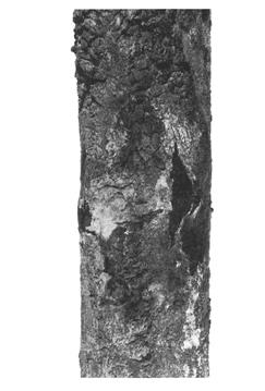
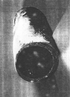
High temperature coal (left) and oil (right) ash corrosion
A hard, brittle surface layer will develop on some alloys due to exposure to high temperature process streams containing high levels of nitrogen compounds such ammonia or cyanides, particularly under reducing conditions. Affected materials are carbon steels, low alloy steels, 300 Series SS and 400 Series SS. Nickel base alloys are more resistant.
Nitriding is a diffusion controlled process dependent on temperature, time, partial pressure of nitrogen and metal composition. Temperatures must be high enough to allow for the thermal breakdown/disassociation of nitrogen from ammonia or other compounds and for diffusion of nitrogen into the metal. Nitriding begins above 320°C and becomes severe above 480°C. High gas phase nitrogen activity (high partial pressures of nitrogen) promotes nitriding. Corrosion resistance may be adversely affected by nitriding. Alloys containing 30% to 80% nickel are more resistant. A loss of high temperature creep strength, ambient temperature mechanical properties (specifically toughness/ductility), weldability and corrosion resistance may result.
Affected Units or Equipment
Nitriding can occur at any location where appropriate environment and temperature conditions are met, but it is considered to be fairly rare. Nitriding has been observed in steam methane-reformers, steam gas cracking (olefin plants) and ammonia synthesis plants.
Appearance or Morphology of Damage
Nitriding is usually confined to the surface of most components and will have a dull, dark gray appearance. However, during initial stages of nitriding, damage can only be seen with metallography. In a more advanced stage, the material will exhibit very high surface hardness. In most cases, a slightly harder surface layer of a vessel or component will not affect the mechanical integrity of the equipment. However, the concern is for the potential development of cracks in the nitrided layer that could propogate into the base metal. Nitriding of low alloy steels containing up to 12% chromium is accompanied by an increase in volume. The nitrided layer tends to crack and flake. Above 410°C, preferential grain boundary nitriding may lead to microcracking and embrittlement. Stainless steels tend to form thin, brittle layers that may crack and spall from thermal cycling or applied stress. Nitrogen diffuses into the surface and forms needle-like particles of iron nitrides (Fe3N or Fe4N) that can only be confirmed by metallography.
Prevention / Mitigation
Changing to more resistant alloys with 30% to 80% nickel is usually required. It is usually not practical to modify the process conditions to reduce the nitrogen partial pressure or to lower temperatures.
Inspection and Monitoring
A change in surface color to a dull gray may indicate nitriding. Materials exposed to nitriding conditions should be inspected thoroughly because good appearance may mask damage. Hardness testing of the affected surfaces (400 to 500 BHN or higher) can help indicate nitriding. Nitrided layers are magnetic. Therefore, 300 Series SS should be checked for magnetism as an initial screening. Metallography is generally required to confirm nitriding. EC testing may be used in some cases to detect nitriding. In the advanced stages of nitriding, where cracking may have initiated, appropriate inspection techniques include PT, RT and UT.
A nitrided 5Cr-0.5Mo thermowell from an ammonia synthesis plant with surface cracking.
Environment Assisted Cracking
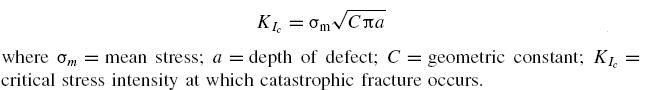
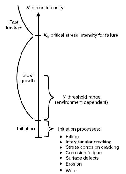
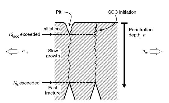
Fracture Mechanics "Crash course"
Surface initiated cracks caused by environmental cracking of 300 Series SS and some nickel base alloys under the combined action of tensile stress, temperature and an aqueous chloride environment. The presence of dissolved oxygen increases propensity for cracking. All 300 Series SS are highly susceptible. Duplex stainless steels are more resistant. Nickel base alloys are highly resistant.
Chloride content, pH, temperature, stress, presence of oxygen and alloy composition are critical factors. Increasing temperatures increase the susceptibility to cracking. Increasing levels of chloride increase the likelihood of cracking. No practical lower limit for chlorides exists because there is always a potential for chlorides to concentrate. Heat transfer conditions significantly increase cracking susceptibility because they allow chlorides to concentrate. Alternate exposures to wet-dry conditions or steam and water are also conducive to cracking. SCC usually occurs at pH values above 2. At lower pH values, uniform corrosion generally predominates. SCC tendency decreases toward the alkaline pH region. Cracking usually occurs at metal temperatures above about 60°C, although exceptions can be found at lower temperatures. Stress may be applied or residual. Highly stressed or cold worked components, such as expansion bellows, are highly susceptible to cracking. Oxygen dissolved in the water normally accelerates SCC but it is not clear whether there is an oxygen concentration threshold below which chloride SCC is impossible. Nickel content of the alloy has a major affect on resistance. The greatest susceptibility is at a nickel content of 8% to 12%. Alloys with nickel contents above 35% are highly resistant and alloys above 45% are nearly immune. Low-nickel stainless steels, such as the duplex (ferrite-austenite) stainless steels, have improved resistance over the 300 Series SS but are not immune. Carbon steels, low alloy steels and 400 Series SS are not susceptible to Cl-SCC .
Affected Units or Equipment
All 300 Series SS piping and pressure vessel components in any process units are susceptible to Cl- SCC. Cracking has occurred in water-cooled condensers and in the process side of crude tower overhead condensers. Drains in hydroprocessing units are susceptible to cracking during startup/shutdown if not properly purged. Bellows and instrument tubing, particularly those associated with hydrogen recycle streams contaminated with chlorides, can be affected. External Cl–SCC has also been a problem on insulated surfaces when insulation gets wet. Cracking has occurred in boiler drain lines.
Appearance or Morphology of Damage
Surface breaking cracks can occur from the process side or externally under insulation. The material usually shows no visible signs of corrosion. Characteristic stress corrosion cracks have many branches and may be visually detectable by a craze cracked appearance of the surface. Metallography of cracked samples typically shows branched transgranular cracks. Sometimes intergranular cracking of sensitized 300 Series SS may also be seen. Welds in 300 Series SS usually contain some ferrite, producing a duplex structure that is usually more resistant to Cl–SCC. Fracture surfaces often have a brittle appearance.
Prevention / Mitigation
Use resistant materials of construction. When hydrotesting, use low chloride content water and dry out thoroughly and quickly. Properly applied coatings under insulation. Avoid designs that allow stagnant regions where chlorides can concentrate or deposit. A high temperature stress relief of 300 Series SS after fabrication may reduce residual stresses. However, consideration should be given to the possible effects of sensitization that may occur, increasing susceptibility to polythionic SCC, possible distortion problems and potential reheat cracking.
Inspection and Monitoring
Cracking is surface connected and may be detected visually in some cases. PT or phase analysis EC techniques are the preferred methods. Eddy current inspection methods have also been used on condenser tubes as well as piping and pressure vessels. Extremely fine cracks may be difficult to find with PT. Special surface preparation methods, including polishing or high-pressure water blast, may be required in some cases, especially in high pressure services. UT, as well as often, RT is not sufficiently sensitive to detect cracks except in advanced stages where a significant network of cracks has developed.
External cracking of Type 304SS instrument tubing under insulation
Typical manifestations of Cl-SCC
A form of fatigue cracking in which cracks develop under the combined affects of cyclic loading and corrosion. Cracking often initiates at a stress concentration such as a pit in the surface. Cracking can initiate at multiple sites. Affected are all metals and alloys.
The critical factors are the material, corrosive environment, cyclic stresses and stress raisers. Cracking is more likely to occur in environments that promote pitting or localized corrosion under cyclic stress due to thermal stress, vibration or differential expansion. Contrary to a pure mechanical fatigue, there is no fatigue limit load in corrosion-assisted fatigue. Corrosion promotes failure at a lower stress and number of cycles than the materials’ normal endurance limit in the absence of corrosion and often results in propagation of multiple parallel cracks. Crack initiation sites include concentrators such as pits, notches, surface defects, changes in section or fillet welds.
Affected Units or Equipment
Rotating equipment, deaerators and cycling boilers, as well as any equipment subjected to cyclic stresses in a corrosive environment. Some examples include:
a) Rotating Equipment - Galvanic couples between the impeller and the pump shaft or other corrosion mechanisms may result in a pitting problem on the shaft. The pitting can act as a stress concentrator or stress riser to promote cracking. Most cracking is transgranular with little branching.
b) Deaerators - In the late 1980’s, deaerators in the pulp and paper, refining and petrochemical and fossil fueled utility industries had major deaerator cracking problems. Complete vessel failures in the pulp and paper industry resulted in a diligent inspection program that found major cracking problems across the various industries. It was concluded that residual welding and fabrication stresses, stress risers (attachments and weld reinforcement) and the normal deaerator environment could produce multiple corrosion fatigue cracking problems.
c) Cycling Boilers - A cycling boiler may see several hundred cold starts over its useful life which, because of differential expansion, continually cracks the protective magnetite scale, allowing corrosion to continue.
Appearance or Morphology of Damage
The fatigue fracture is brittle and the cracks are most often transgranular, as in stress-corrosion cracking, but not branched, and often results in propagation of multiple parallel cracks. Fatigue cracking will be evidenced by very little plastic deformation except that final fracture may occur by mechanical overload accompanied by plastic deformation. In cycling boilers, the damage usually appears first on the water side of buckstay attachments. The cracking pattern may be circular cracks surrounding the weld between the buckstay attachment and the waterwall tube. In cross-section, the cracks tend to be bulbous with numerous lobes. The crack tips themselves may be somewhat blunted but are oxide filled and transgranular. In sulfidizing environments, cracks will have a similar appearance but will be filled with a sulfide scale. In rotating equipment, most cracking is transgranular with minimal branching.
Prevention / Mitigation
Rotating Equipment
· Modify the corrosive environment by using coatings and/or inhibitors.
· Minimize galvanic couple effects.
· Use more corrosion resistant materials.
Deaerators
· Proper feedwater and condensate chemical control.
· Minimize residual welding and fabrication stresses through PWHT.
· Minimize weld reinforcement by grinding weld contours smooth.
Cycling Boilers
· Start up slowly to minimize the differential expansion strains.
· Always start up with the chemistry of the boiler water under proper control.
Inspection and Monitoring
Rotating Equipment
· UT and MT techniques can be used for crack detection.
Deaerators
· Cracking is generally detected with WFMT inspection.
· Many of the cracks are very tight and difficult to detect.
Cycling Boilers
· The first sign of damage is usually a pinhole leak on the cold side of a waterwall tube at a buckstay attachment.
· Inspect highly stressed regions in the boiler by UT or EMATS techniques.
· Cracking may occur at the membranes in the highly stressed regions, particularly corners at buckstays.
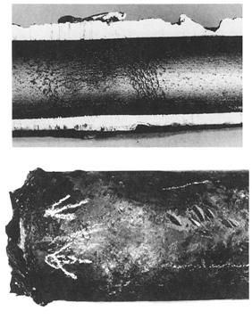
Corrosion fatigue of boiler tubes
Caustic embrittlement is a form of stress corrosion cracking characterized by surface-initiated cracks that occur in piping and equipment exposed to caustic, primarily adjacent to non-PWHT’d welds. Carbon steel, low alloy steels and 300 Series SS are susceptible. Nickel base alloys are more resistant.
Susceptibility to caustic embrittlement in caustic soda (NaOH) and caustic potash (KOH) solutions is a function of caustic strength, metal temperature and stress levels. Increasing caustic concentration and increasing temperatures increase the likelihood and severity of cracking. Conditions likely to result in cracking have been established through plant experience. Cracking can occur at low caustic levels if a concentrating mechanism is present. In such cases, caustic concentrations of 50 to 100 ppm are sufficient to cause cracking. Stresses that promote cracking can be residual that result from welding or from cold working (such as bending and forming) as well as applied stresses. It is generally accepted that stresses approaching yield are required for SCC so that thermal stress relief (PWHT) is effective in preventing caustic SCC. Although failures have occurred at stresses that are low relative to yield, they are considered more rare. Crack propagation rates increase dramatically with temperature and can sometimes grow through wall In a matter of hours or days during temperature excursions, especially if conditions promote caustic concentration. Concentration can occur as a result of alternating wet and dry conditions, localized hot spots or high temperature steamout. Special care must be taken with steam tracing design and steamout of non-PWHT’d carbon steel piping and equipment.
Affected Units or Equipment
Caustic embrittlement is often found in piping and equipment that handles caustic, including H2S and mercaptan removal units, as well as equipment that uses caustic for neutralization in sulfuric acid alkylation units and HF alkylation units. Caustic is sometimes injected into the feed to the crude tower for chloride control. Failures have occurred in improperly heat-traced piping or equipment as well as heating coils and other heat transfer equipment. Caustic embrittlement may occur in equipment as a result of steam cleaning after being in caustic service. Traces of caustic can become concentrated in BFW and can result in caustic embrittlement of boiler tubes that alternate between wet and dry conditions due to overfiring.
Appearance or Morphology of Damage
Caustic stress corrosion cracking typically propagates parallel to the weld in adjacent base metal but can also occur in the weld deposit or heat-affected zones. The pattern of cracking observed on the steel surface is sometimes described as a spider web of small cracks which often initiate at or interconnect with weld-related flaws that serve as local stress raisers. Cracks can be confirmed through metallographic examination as surface breaking flaws that are predominantly intergranular. The cracking typically occurs in as-welded carbon steel fabrications as a network of very fine, oxide-filled cracks. Cracking in 300 Series SS is typically transgranular and is very difficult to distinguish from chloride stress corrosion cracking.
Prevention / Mitigation
Cracking can be effectively prevented by means of a stress-relieving heat treatment (e.g. PWHT). A heat treatment at 620°C is considered an effective stress relieving heat treatment for carbon steel. The same requirement applies to repair welds and to internal and external attachment welds. 300 Series SS offer little advantage in resistance to cracking over CS. Nickel base alloys are more resistant to cracking and may be required at higher temperatures and/or caustic concentrations. Steamout of non-PWHT’d carbon steel piping and equipment should be avoided. Equipment should be water washed before steamout. Where steamout is required, only low-pressure steam should be used for short periods of time to minimize exposure. Proper design and operation of the injection system is required to ensure that caustic is properly dispersed before entering the high-temperature crude preheat system.
Inspection and Monitoring
Although cracks may be seen visually, crack detection is best performed with WFMT, EC, RT or ACFM techniques. Surface preparation by grit blasting, high pressure water blasting or other methods is usually required. PT is not effective for finding tight, scale-filled cracks and should not be used for detection. Crack depths can be measured with a suitable UT technique including external SWUT. AET can be used for monitoring crack growth and locating growing cracks.
Recommended operating limits for carbon steel in caustic service.
Cracking at a boiler tubesheet due to caustic concentrating between the tube and the tubesheet.
Aqueous streams containing ammonia may cause Stress Corrosion Cracking (SCC) in some copper alloys. Carbon steel is susceptible to SCC in anhydrous ammonia.
Susceptible copper alloys may suffer cracking under the combination of residual stress and chemical compounds. Copper-zinc alloys (brasses), including admiralty brass and aluminum brasses, are susceptible. Zinc content of brasses affects susceptibility, especially as zinc increases above 15%. A water phase with ammonia or ammoniacal compounds must be present. Oxygen is necessary, but trace amounts are sufficient. pH above 8.5. Occurs at any temperature. Residual stresses from fabrication or tube rolling are sufficient to promote cracking.
For steel, Anhydrous ammonia with <0.2% water will cause cracking in carbon steel. PWHT eliminates susceptibility of most common steels of lower tensile strength. Contamination with air or oxygen increases tendency toward cracking.
Affected Units or Equipment
Copper-zinc alloy tubes in heat exchangers. Ammonia is present as a process contaminant in some services or may be intentionally added as an acid neutralizer. Carbon steel is used for ammonia storage tanks, piping and equipment in ammonia refrigeration units as well as some lube oil refining processes.
Appearance or Morphology of Damage
Copper alloys - Surface breaking cracks may show bluish corrosion products. Exchanger tubes show single or highly branched cracks on the surface. Cracking can be either transgranular or intergranular, depending on the environment and stress level.
For carbon steel - Cracking will occur at exposed non-PWHT welds and heat affected zones.
Prevention / Mitigation
Copper alloys - Copper-zinc alloys show improved resistance as zinc content decreases below 15%. The 90-10CuNi and 70-30CuNi alloys are nearly immune. SCC in steam service can sometimes be controlled by preventing the ingress of air. 300 Series SS and nickel base alloys are immune.
Carbon steel - SCC of steel can be prevented by PWHT or through the addition of small quantities of water to the ammonia (0.2%). Consideration must be given to vapor spaces could have less than 0.2% water present due to partitioning of ammonia in water phase. Weld hardness should not exceed 225 BHN. Prevent ingress of oxygen into storage facilities.
Inspection and Monitoring
For copper alloys - Monitor pH and ammonia of water draw samples to assess susceptibility of copper alloys. Inspect heat exchanger tubes for cracking using EC or visual inspection. Rolled area is highly susceptible.
For steel storage tanks and or piping in anhydrous ammonia - WFMT welds inside tanks. External UT Shear wave.
Cross-section of a brass exchanger tube showing transgranular cracking
Liquid Metal Embrittlement (LME) is a form of cracking that results when certain molten metals come in contact with specific alloys. Cracking can be very sudden and brittle in nature.
Many commonly used materials including carbon steel, low alloy steels, high strength steels, 300 Series SS, nickel base alloys and the copper alloys, aluminum alloys and titanium alloys are affected.
LME occurs in very specific combinations of metals in contact with low melting point metals such as zinc, mercury, cadmium, lead, copper and tin. Typical combinations of industrial significance are shown in table below.
|
Susceptible Alloy
|
Molten Metal
|
|
300 Series SS
|
Zinc
|
|
Copper Alloys
|
Mercury
|
|
Alloy 400
|
Mercury
|
|
Aluminum Alloys
|
Mercury
|
|
High Strength Steels
|
Cadmium, Lead
|
High tensile stress promotes cracking, however, cracking can initiate simply through contacting the molten metal with the susceptible alloy. Very small quantities of the low melting point metal are sufficient to cause LME. Tensile stress contributes to crack propagation rates. Cracking under load can be extremely rapid such that cracks may pass through the wall within seconds of contact with the molten metal. Cracking can occur after long periods of time when contaminated surfaces are exposed to liquid metals. A susceptible metal in contact with a low melting metal at low temperatures may crack later when the temperature rises above the melting temperature of the low melting alloy.
Affected Units or Equipment
During a fire, molten metals may drip onto or contanct a susceptible metal. Examples include melted zinc galvanizing, cadmium electrical housings, tin or lead from solders, and melted copper components. LME can occur in any location where the LME couples are found. A common example is 300 Series SS piping or vessels in contact with (or previously rubbed against) galvanized steel In refineries, mercury is found in some crude oils and can condense in the atmospheric tower overhead system thereby embrittling brass, Alloy 400, titanium or aluminum exchanger components. Failure of process instruments that utilize mercury can introduce the liquid metal into refinery streams LME of aluminum components has occurred in cryogenic gas plant components due to condensation of liquid mercury.
Appearance or Morphology of Damage
Damage resulting from LME will appear as brittle cracks in an otherwise ductile material. LME can only be confirmed through metallography by the presence of intergranular cracks, usually filled with the low melting metal. Techniques such as spectrographic analysis may be required to confirm the presence of the molten metal species.
Prevention / Mitigation
LME can only be prevented by protecting metal substrates from coming into contact with the low melting metal. For example, galvanized steel components should not be welded to 300 Series SS. 300 Series SS should be protected to avoid contact with galvanized components and overspray from zinc and inorganic zinc coatings.
Once cracking from LME has initiated, grinding out the affected area is not an acceptable fix.
Inspection and Monitoring
Cracks can be detected with MT examination for ferritic steel and PT examination for 300 Series SS and nickel base alloys. Because of the high density of mercury, radiography has been used to locate deposits inside heat exchanger tubes.
Optical micrograph of copper penetration (liquid metal embrittlement) in the broken axles
Liquid metal embrittlement of Monel caused by mercury in an FCC gas plant overhead drum
A loss in ductility of high strength steels due to the penetration of atomic hydrogen can lead to brittle cracking. Hydrogen Embrittlement (HE) can occur during manufacturing, welding, or from services that can charge hydrogen into the steel in an aqueous, corrosive, or a gaseous environment. Affected materials are Carbon steel and low alloy steels, 400 Series SS, Precipitation Hardenable (PH) SS and some high strength nickel base alloys. Three conditions must be satisfied:
· Hydrogen must be present at a critical concentration within the steel/alloy.
· The strength level and microstructure of the steel/alloy must be susceptible to embrittlement.
· A stress above the threshold for HE must be present from residual stresses and/or applied stresses.
The hydrogen can come from:
· Welding – if wet electrodes or high moisture content flux weld electrodes are used, hydrogen can be charged into the steel (delayed cracking).
· Cleaning and pickling in acid solutions.
· Service in high temperature hydrogen gas atmospheres, molecular hydrogen dissociates to form atomic hydrogen that can diffuse into the steel.
· Wet H2S services or HF acid services in which atomic hydrogen diffuses into the steel. (Cyanides, arsenic and FeS can act as hydrogen recombination poisons that diminish the hydrogen gas reaction and allows for greater charging rates.)
· Manufacturing – melting practices or manufacturing processes particularly where components are plated (hydrogen flaking).
· Cathodic protection.
The effect is pronounced at temperatures from ambient to about 150°C. Effects decrease with increasing temperature and HE is not likely to occur above 70°C to 80°C. HE affects static properties to a much greater extent than impact properties. If the hydrogen is present and a sufficient stress is applied, failure can occur quickly. The ammount of trapped hydrogen depends on the environment, surface reactions and the presence of hydrogen traps in the metal such as imperfections, inclusions and pre-existing flaws or cracks. The amount of hydrogen needed to have a measurable effect on the mechanical properties varies with the strength level, microstructure and heat treatment for the alloy. In some cases, thresholds of critical hydrogen concentrations have been established. Stresses include cooling during manufacture, residual stresses from welding or applied loads. Thick wall components are more vulnerable due to increased thermal stress and high restraint and take longer for hydrogen to diffuse out. In general, as strength increases, susceptibility to HE increases. Certain microstructures, such as untempered martensite and pearlite, are more susceptible at the same strength level than tempered martensite. Carbon steel that is severely hydrogen charged will have lower toughness than with no hydrogen.
Affected Units or Equipment
Services where HE is a concern include cabon steel piping and vessels in wet H2S services in FCC, hydroprocessing, amine, sour water services and HF alkylation units. However, mild steel used for vessels and piping in most refining, fossil utility and process applications have low hardness and are usually not susceptible to HE except at weldments, particularly the HAZ, if suitable PWHT is not performed. Storage spheres are often made of slightly higher strength steels and are more susceptible than most other refinery equipment. Bolts and springs made of high strength steel are very prone to HE. (Alloys that have a tensile strength above 150 ksi can absorb hydrogen during electroplating and crack.) Cr-Mo reactors, drums and exchanger shells on hydroprocessing units and catalytic reforming units are susceptible if the weld heat affected zone hardness exceeds 235 BHN.
Appearance or Morphology of Damage
Cracking due to HE can initiate sub-surface, but in most cases is surface breaking. HE occurs at locations of high residual or tri-axial stresses (notches, restraint) and where the microstructure is conducive, such as in weld HAZ’s. On a macro-scale, there is often little evidence, although some materials will appear to have brittle fracture surfaces. On a microscale, the material will contain less ductile fracture surface, but must often be compared to a fracture without the presence of hydrogen. In higher strength steels, cracking is often intergranular.
Prevention / Mitigation
Dependent on the source of the hydrogen, alloy composition and fabrication/heat treatment history. Use lower strength steels and PWHT to temper the microstructure, improve ductility and reduce residual stresses and hardness. During welding, use low hydrogen, dry electrodes and preheating methods. If hydrogen is expected to have diffused into the metal, an elevated temperature bake out [204°C or higher] may be required to drive the hydrogen out prior to welding. Heavy wall equipment in hot hydrogen service requires controlled shutdown and start-up procedures to control the pressurization sequence as a function of temperature. In corrosive aqueous services, apply a protective lining, SS cladding or weld overlay to prevent the surface hydrogen reactions.
Inspection and Monitoring
For surface cracking inspection use PT, MT or WFMT. UT may also be useful in finding HE cracks. RT often is not sufficiently sensitive to detect HE cracks. If the source of hydrogen is a low temperature aqueous environment, hydrogen flux can be monitored using specialized instruments.
Hydrogen embrittlement crack in a thick-wall 2.25Cr – 1Mo exchanger channel circumferential weld. Hardness = 235 BHN
Damage mechanisms specific for refining industry
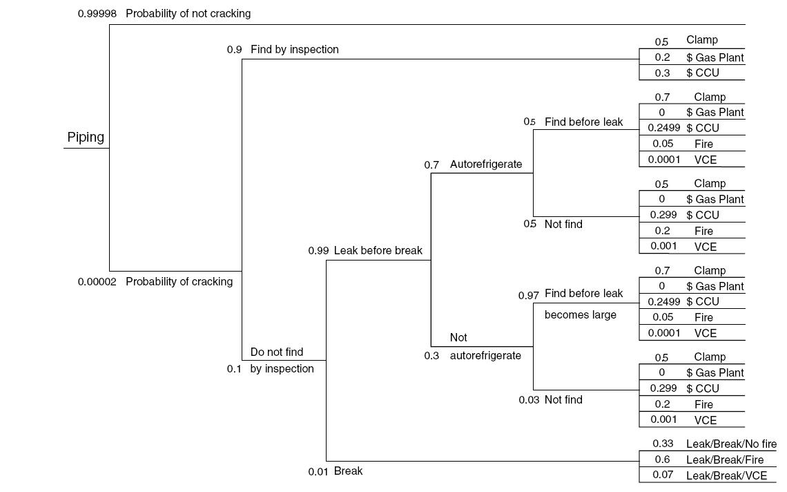
Scenario building FCC Piping. Why we need POD?
Uniform or Localized Loss in Thickness Phenomena
Amine corrosion refers to the general and/or localized corrosion that occurs principally on carbon steel in amine treating processes. Corrosion is not caused by the amine itself, but results from dissolved acid gases (CO2 and H2S), amine degradation products, Heat Stable Amine Salts (HSAS) and other contaminants. Affected materials are primarily carbon steel. 300 Series SS are highly resistant.
Corrosion depends on design and operating practices, the type of amine, amine concentration, contaminants, temperature and velocity. Amine corrosion is very closely tied to the operation of the unit. With a few exceptions, carbon steel is suitable for most components in a properly designed and operated unit. Most problems can be traced to faulty design, poor operating practices or solution contamination. Corrosion is also dependent on the type of amine used. In general, alkanolamine systems can be rated in order of aggressiveness from most to least as follows: monoethanolamine (MEA), diglycolamine (DGA), diisopropylamine (DIPA), diethanolamine (DEA), and methyldiethanolamine (MDEA). Lean amine solutions are generally not corrosive because they have either low conductivity and or high pH. However, an excessive accumulation of heat stable amine salts (HSAS) above about 2%, depending on the amine, can significantly increase corrosion rates. Ammonia, H2S and HCN accelerate corrosion in the regenerator overhead condenser and outlet piping as well as reflux piping, valves and pumps. Corrosion rates increase with increasing temperature, particularly in rich amine service. Temperatures above about 100°C can result in acid gas flashing and severe localized corrosion if the pressure drop is high enough. Process stream velocity will influence the amine corrosion rate and nature of attack. Corrosion is generally uniform however high velocities and turbulence will cause localized thickness losses. For carbon steel, common velocity limits are generally limited to 3 to 6 fps for rich amine and about 20 fps for lean amine.
Affected Units or Equipment
Amine units are used in refineries to remove H2S, CO2 and mercaptans from process streams originating in many units including the crude, coker, FCC, hydrogen reforming, hydroprocessing, and tail gas units. The regenerator reboiler and the regenerator are areas where the temperature and turbulence of the amine stream are the highest and can cause significant corrosion problems. The rich amine side of the lean/rich exchangers, hot lean amine piping, hot rich amine piping, the amine solution pumps, and the reclaimers are also areas where corrosion problems occur.
Appearance or Morphology of Damage
Carbon steel and low alloy steels suffer general uniform thinning, localized corrosion or localized underdeposit attack Thinning will be uniform in nature when the process stream velocity is low while it will be localized for high velocities associated with turbulence.
Prevention / Mitigation
Proper operation of the amine system is the most effective way to control corrosion, with particular attention to acid gas loading levels. In addition, to avoid corrosive amine degradation products, the process temperature should not exceed recommended limits. Proper control of the reboiler rate and temperature is necessary in order to maintain a regenerator top temperature. Proper attention should be given to avoid the buildup of HSAS to unacceptable levels. The system design should incorporate measures to control local pressure drop to minimize flashing. In areas where it is unavoidable, upgrading to 300 Series SS or other corrosion resistant alloys may be required. SS410 trays and internals are also used in absorber and stripping towers. Oxygen inleakage causes high corrosion rates and contributes to heat stable salt formation. Storage tanks and surge vessels should be blanketed with inert gas. Solids and hydrocarbons should be removed from the amine solution by filtration and through process control. Filtration of rich amine solutions has the potential to be more effective than lean amine filtration for solids removal. Corrosion inhibitors may be required to control amine corrosion within acceptable levels.
Inspection and Monitoring
Visual examination and UT thickness measurement are the methods used for internal equipment inspection. UT scans or profile radiography are used for external inspection. Corrosion monitoring can also be achieved with corrosion coupons and/or corrosion probes. Monitoring should target the hot areas of the unit such as the reboiler feed and return line, the hot lean/rich amine piping, and the stripper overhead condenser piping.
Localized amine corrosion at the weld found in piping from reboiler to regenerator tower in an MEA unit. Many other similar cases found, some going as deep as half thickness. They were originally found and mistaken as cracks with shear wave UT inspection.
Aggressive corrosion occurring in hydroprocessing reactor effluent streams and in units handling alkaline sour water. Several major failures have occurred in hydroprocessing reactor effluent systems due to localized corrosion.
Affected materials - Carbon steel is less resistant, 300 Series SS, duplex SS, aluminum alloys and nickel base alloys are more resistant, depending on ammonium bisulfide (NH4HS) concentration and velocity.
NH4HS concentration, velocity and/or localized turbulence, pH, temperature, alloy composition and flow distribution are all critical factors to consider. Corrosion increases with increasing NH4HS concentration and increasing velocity. Below 2 wt %, solutions are not generally corrosive. Above 2 wt %, solutions are increasingly corrosive. In hydroprocessing reactors, FCC reactors and coker furnaces, nitrogen in the feed is converted to ammonia and reacts with H2S to form NH4HS. NH4HS precipitates out of the gas phase in the reactor effluent stream at temperatures below about 150oF (66oC), depending on the concentration of NH3 and H2S, and may cause fouling and plugging unless flushed away with wash water. NH4HS salt deposits lead to underdeposit corrosion and fouling. Oxygen and iron in the wash water injected into hydroprocessing reactor effluent can lead to increased corrosion and fouling.
Presence of cyanides increases severity of corrosion in FCC gas plants, coker gas plants and sour water stripper overheads by destroying the normally protective sulfide film.
Affected Units or Equipment
Hydroprocessing Units - NH4HS salts precipitate in the reactor effluent streams when temperatures drop to within the range of 50°C to 66°C. Fouling and/or velocity accelerated corrosion may be found at:
· Air cooler header boxes.
· Inlet and outlet piping of air coolers, as well as exchanger tubes.
· Piping into and out of the reactor effluent separators.
· Sour water draw piping from reactor effluent separators; flashing may cause severe erosioncorrosion downstream of control valves
· Vapor line from the high pressure separators.
· Hydrocarbon lines from reactor effluent separators due to entrained sour water.
· Stripper Column overhead sour water.
FCC Units - NH4HS concentrations are usually less than 2 wt % but high velocities and/or the presence of cyanides can remove protective iron sulfide scales.
Sour Water Strippers (SWS) - High concentrations of NH4HS in stripper overhead piping, condensers, accumulator and reflux piping, and possible presence of cyanides.
Amine Units - High concentrations of NH4HS may be found in regenerator overheads and reflux piping depending on unit operation.
Delayed Coker - High concentrations of NH4HS may be found in the gas concentration plant downstream of the fractionator tower.
Appearance or Morphology of Damage
General loss in thickness of carbon steel, with the potential for extremely high localized rates of wall loss can occur at changes in direction or turbulent flow areas above 2 wt % concentration. Low velocities may result in extremely localized under-deposit corrosion if insufficient water is available to dissolve the NH4HS salts that precipitated. Heat exchangers may show plugging and loss of duty due to fouling. NH4HS rapidly corrodes admiralty brass tubes and other copper alloys.
Prevention / Mitigation
Good design practice should consist of symmetrical and hydraulically balanced flow in and out of air cooled exchangers. Carefully review design and localized velocities as process conditions change, particularly as NH4HS concentrations exceed 2 wt % and begin to approach 8 wt % or higher. Maintain velocities within industry guidelines of 10 to 20 fps for carbon steel. Carbon steel may be susceptible to high corrosion rates above about 8 wt % NH4HS concentration Use resistant materials of construction (e.g. Alloy 825, duplex SS) at velocities above 20 fps, depending on NH4HS concentration. Properly design and maintain water wash injection with low oxygen content; provide sufficient excess water to ensure that an adequate amount of water remains as liquid to dilute the NH4HS salts. Use proper injection spray nozzles and metallurgy. Titanium and Alloy C276 have been used in overhead condensers in SWS units. Aluminum exchanger tubes are extremely susceptible to erosion-corrosion damage.
Inspection and Monitoring
A carefully designed plan should include input from process engineers and materials/corrosion engineers to determine specific areas of vulnerability. Determine ammonium bisulfide content through sampling and calculation. Frequent UT scanning and/or RT profile thickness of high and low velocity areas. UT downstream of control valves at high NH4HS concentrations. IRIS, RFEC and flux leakage inspection of steel air cooler tubes. EC inspect non-magnetic air cooler tubes. Monitor water injection facilities and flow meters to ensure proper operation.
2-inch CS elbow and straight section in a sour water line off the cold HPS on an HDT unit.
General or localized corrosion, often pitting, normally occurring under ammonium chloride or amine salt deposits, often in the absence of a free water phase. All commonly used materials are susceptible, in order of increasing resistance: carbon steel, low alloy steels, 300 Series SS, Alloys 400, duplex SS, 800, and 825, Alloys 625 and C276 and titanium.
Concentration (NH3, HCl, H20 or amine salts), temperature and water availability are the critical factors. Ammonium chloride salts may precipitate from high temperature streams as they are cooled, depending upon the concentration of NH3 and HCl, and may corrode piping and equipment at temperatures well above the water dewpoint 150°C. Ammonium chloride salts are hygroscopic, and readily absorb water. A small amount of water can lead to very aggressive corrosion [>100 mpy (>2.5 mm/y]. Ammonium chloride and amine hydrochloride salts are highly water soluble, highly corrosive and form an acidic solution when mixed with water. Some neutralizing amines react with chlorides to form amine hydrochlorides that can act in a similar fashion. Corrosion rates increase with increasing temperature. When they deposit above the water dewpoint, a water wash injection may be required to dissolve the salts.
Affected Units or Equipment
Crude Tower Overheads - Tower top, top trays, overhead piping and exchangers may be subject to fouling and corrosion. Deposits may occur in low flow zones due to ammonia and/or amine chloride salts condensing from the vapor phase. Top pumparound streams may be affected if ammonia or amine chloride salts are present.
Hydroprocessing - Reactor effluent streams are subject to ammonium chloride salt fouling and corrosion. Water washing may be required if exchanger fouling or loss in duty occurs.
Catalytic Reforming - Reactor effluent streams and the H2 recycle system are subject to ammonium chloride salting and corrosion. FCCU and coker fractionator overheads and top pumparounds are subject to ammonium chloride corrosion and salting.
Appearance or Morphology of Damage
The salts have a whitish, greenish or brownish appearance. Water washing and/or steamout will remove deposits so that evidence of fouling may not be evident during an internal visual inspection. Corrosion underneath the salts is typically very localized and results in pitting. Corrosion rates can be extremely high.
Prevention / Mitigation
Alloys that are more pitting resistant will have improved resistance to ammonium chloride salts but even the most corrosion resistant nickel base alloys and titanium alloys may suffer pitting corrosion.
Crude Unit - Limit salts by limiting chlorides in the tower feed through desalting and/or the addition of caustic to the desalted crude. A water wash may be required in the crude tower overhead line to flush the salt deposits. Filming amine inhibitors are often added to control corrosion.
Hydroprocessing - Limit chlorides in the hydrocarbon feed to the reactor. Limit chlorides in the make-up hydrogen supply. A continuous or intermittent water wash may be required in the reactor effluent to flush out the salt deposits.
Catalytic Reforming - Reactor effluent can be treated to remove the chlorides. Water washing has been used in some cases but the system must be carefully designed. Some tower overheads may require neutralizing or filming amines.
Inspection and Monitoring
Accumulation of ammonium chloride salts can be very localized and the resulting corrosion may be difficult to detect. RT or UT thickness monitoring can be used to determine remaining wall thickness. Monitoring of the feed streams and effluent waters will give an indication of the amount of ammonia and chlorides present, however process simulation may be required to determine the concentration and dewpoint temperatures. If the ammonium chloride salt deposition temperature has been calculated, temperature monitoring and control may be effective for maintaining metal temperatures above the salt deposition temperature.
The presence of deposits is often detected when the pressure drop increases or the thermal performance of exchangers has deteriorated. Corrosion probes or coupons can be useful, but the salt must deposit on the corrosion probe element to detect the corrosion.
Hydrochloric acid (aqueous HCl) causes both general and localized corrosion and is very aggressive to most common materials of construction across a wide range of concentrations. Damage in refineries is most often associated with dew point corrosion in which vapors containing water and hydrogen chloride condense from the overhead stream of a distillation, fractionation or stripping tower. The first water droplets that condense can be highly acidic (low pH) and promote high corrosion rates. Affected materials are all common materials of construction used in refineries.
HCl acid concentration, temperature and alloy composition are critical factors. The severity of corrosion increases with increasing HCl concentration and increasing temperature. Aqueous HCl can form beneath deposits of ammonium chloride or amine hydrochloride salts in exchangers and piping. The deposits readily absorb water from the process stream or from injected wash water. Hydrogen chloride is normally not corrosive in dry process streams, but becomes very corrosive where water is available to form hydrochloric acid. Carbon steel and low alloy steels are subject to excessive corrosion when exposed to any concentration of HCl acid that produces at pH below about 4.5.
300 series SS and 400 series SS are not usefully resistant to HCl at any concentration or temperature. Alloy 400, titanium and some other nickel base alloys have good resistance to dilute HCl acid in many refinery applications. The presence of oxidizing agents (oxygen, ferric and cupric ions) will increase the corrosion rate, particularly for alloy 400 and Alloy B-2. Titanium performs well in oxidizing conditions but fails rapidly in dry HCl service.
Affected Units or Equipment
HCl corrosion is found in several units, especially crude and vacuum units, hydroprocessing units and catalytic reformer units.
Crude Unit - In the atmospheric tower overhead system, corrosion from HCl acid occurs as the first droplets of water condense from the vapor stream off the top of the tower. This water can have a very low pH and can result in high rates of corrosion in piping, as well as exchanger shells, tubes and header boxes, and cold dead legs. HCl corrosion can also be a problem in the vacuum ejector and condensing equipment off the top of the vacuum tower.
Hydroprocessing Units - Chlorides may enter the unit as organic chloride in the hydrocarbon feed or with the recycle hydrogen and react to form HCl. Ammonium chloride salts can form in various parts of the unit including the effluent side of the hot feed/effluent exchangers because both NH3 and HCl are present or they may condense with water in the effluent train. HCl containing streams can migrate through the fractionation section resulting in severe acid dewpoint corrosion at the mixing point where it contacts water.
Catalytic Reforming Units - Chlorides may be stripped from the catalyst and react to form HCl that carries through the effluent train, regeneration system, stabilizer tower, debutanizer tower and feed/preheat exchangers. HCl containing vapors can migrate through the gas plant fractionation section resulting in mix point or acid dew point corrosion.
Appearance or Morphology of Damage
Carbon steel and low alloy steels suffer general uniform thinning, localized corrosion or under deposit attack. 300 Series SS and 400 Series SS will often suffer pitting attack and 300 Series SS may experience chloride stress corrosion cracking.
Prevention/Mitigation
Crude Units - Optimize the crude oil tank water separation and withdrawal and crude desalting operation to reduce chloride in the feed to the crude tower. A common target is 20 ppm or fewer chlorides in the overhead accumulator water. Upgrading carbon steel to nickel base alloys or titanium can reduce HCl acid corrosion problems. Titanium tubes will solve most overhead condenser tube corrosion problems. Water washing can be added to quench the overhead stream and to help dilute the condensing hydrochloric acid concentration. Caustic injection downstream of the desalter is another common method used to reduce the amount of HCl going overhead. Proper design and operating guidelines must be used to avoid caustic SCC and fouling in the feed preheat train. Various combinations of ammonia, neutralizing amines and filming amines can be injected in the atmospheric tower overhead line before the water dewpoint.
Hydrodroprocessing - Minimize carryover of water and chloride salts from upstream units including neutralizing amine hydrochloride salts. Minimize HCl in H2 streams (e.g., install scrubbers or guard beds to remove Cl- ions from hydrogen produced in catalytic refoming units). Selective use of corrosion resistant nickel base alloys.
Catalytic Reforming - Same as hydroprocessing, but in addition, water washing the hydrocarbon stream has also been used to remove the highly water soluble chlorides. Special care in the design and operation of this equipment is recommended. Minimizing water and/or oxygenates in the feed will reduce stripping of chlorides from the catalyst. Special adsorbents in chloride beds and chloride treaters can be used to remove chlorides from the recycle hydrogen streams and from liquid hydrocarbon streams.
Inspection and Monitoring
For carbon steel, damage is usually in the form of general thinning but may be highly localized where a water phase is condensing. Serious corrosion can also be found at mix points where dry chloride containing streams mix with streams containing free water or where water saturated streams are cooled below the dewpoint. Evidence of locally thinned areas can be found using automatic ultrasonic scanning methods or profile radiography. Process and corrosion monitoring are important aspects of a well-developed program to minimize the effects of HCl corrosion. The pH of the water in the boot of the atmospheric tower overhead accumulator is normally checked every shift. Other variables including chloride and iron content are checked on a less frequent basis but do need to be monitored regularly. Water phases in other units are also monitored by periodic sampling of water draws from the overhead drums of fractionating or stripping towers. Strategically placed corrosion probes and/or corrosion coupons can provide additional information on the rate and extent of damage.
The presence of hydrogen in H2S streams increases the severity of high temperature sulfide corrosion at temperatures above about 260°C. This form of sulfidation usually results in a uniform loss in thickness associated with hot circuits in hydroprocessing units. Affected materials, In order of increasing resistance are: carbon steel, low alloy steels, 400 Series SS, and 300 Series SS.
The major factors affecting high temperature sulfidation are the temperature, the presence of hydrogen, the concentration of H2S and the alloy composition. When hydrogen is present in significant quantities, corrosion rates are higher than those associated with high temperature sulfidation in the absence of hydrogen . Sulfidation rates increase with increasing H2S content and especially increasing temperature. Higher corrosion rates are found more in gas oil desulfurizers and hydrocrackers than naphtha desulfurizers by a factor of almost ‘2’. Susceptibility to sulfidation is determined by the chemical composition of the alloy. Increasing chromium content of the alloy improves resistance. However, there is little improvement with increasing chromium content until about 7-9Cr as shown by the relative rate reduction factors. Chromium-containing nickel base alloys are similar to stainless steel. Similar levels of chromium provide similar corrosion resistance.
Affected Units or Equipment
This form of corrosion occurs in piping and equipment in units where high temperature H2/H2S streams are found including all hydroprocessing units such desulfurizers, hydrotreaters and hydrocracking units. Noticeable increases in corrosion may be found downstream of hydrogen injection points.
Appearance or Morphology of Damage
Corrosion will appear as a uniform loss in thickness from the process side and is accompanied by the formation of an iron sulfide scale. Scale is about 5 times the volume of lost metal and may be in multiple layers. The tightly adherent shiny gray scale attached to the surface may be mistaken for unaffected metal.
Prevention / Mitigation
The corrosion damage is minimized by using alloys with high chromium content. The 300 Series SS such as Types 304L, 316L, 321 and 347 are highly resistant at service temperatures.
Inspection and Monitoring
UT, VT and RT thickness readings are used to monitor loss in thickness. Actual operating temperatures should be verified in the field to compare against design. Process simulations should be checked periodically to confirm that H2S levels have not significantly increased.
Corrosion by HF acid can result in high rates of general or localized corrosion and may be accompanied by hydrogen cracking, blistering and/or HIC/SOHIC. Affected materials .- Carbon steel, copper-nickel alloys, Alloy 400. Other nickel base alloys such as Alloy C276 have also been used in some applications. Low alloy steels, 300 Series SS and the 400 Series SS are susceptible to corrosion and/or cracking and are genmerally not suitable for HF service.
HF acid concentration (water content), temperature, alloy composition and the presence of contaminants including oxygen and sulfur compounds are the controlling factors. Carbon steel forms a protective fluoride scale in dry concentrated acid. Loss of the protective scale through high velocities or turbulence, will result in greatly accelerated corrosion rates. The presence of water can destabilize the fluoride scale and convert it into a voluminous nonprotective scale. The primary concern is the “HF-in-water” concentration of the acid phase. Although the process stream may be comprised primarily of hydrocarbon, the acid is considered as a separate phase. Concentration is determined by the amount of water present in the acid phase. Typical HF alkylation units operate with 1% to 3% water in the acid, equivalent to an HF-in-water concentration of 97% to 99% and the temperatures are generally below 65°C. Under these conditions carbon steel is widely used for all equipment except where close tolerances are required for operation (i.e., pumps, valves, instruments). Corrosion rates increase with increasing temperature and decreasing HF concentration (increasing water content). In carbon steel, residual elements (%Cu, %Ni, %Cr) may accelerate corrosion in certain parts of the unit but industry recommended guidelines have not been formally developed. Some users limit the total Residual Element (RE) content to 0.20% maximum, where RE= %Cu + %Ni +%Cr. Oxygen contamination increases the corrosion rate of carbon steel and promotes accelerated corrosion and SCC of Alloy 400.
Affected Units or Equipment
Piping and equipment in the HF alkylation unit, flare piping and downstream units exposed to acid carryover are also affected. Most equipment is made from carbon steel with the exception of the HF acid rerun/regenerator tower and the acid relief neutralizer vessel which are usually made partially or completely from Alloy 400. High corrosion rates have been observed:
i) In piping and equipment operating above 65°C
ii) In deadlegs including inlets to relief valves, as well as small bore vents and drains;
iii) Condensing overhead vapors in piping and exchangers off top of the Isostripper, Depropanizer and HF Stripper/Propane Stripper;
iv) On flange faces;
v) Heat exchanger bundles that heat acid-containing streams such as the acid vaporizer.
Severe fouling due to iron fluoride corrosion product has been observed in the piping, heat exchangers and in the tops of the Isostripper and Depropanizer towers.
Appearance or Morphology of Damage
Corrosion is in the form of localized general or severe thinning of carbon steel. Corrosion may be accompanied by cracking due to hydrogen stress cracking, blistering and/or HIC/SOHIC damage. Significant fouling due to iron fluoride scales may also accompany corrosion. Alloy 400 shows uniform loss in thickness but is not accompanied by significant scaling. Non-stress relieved Alloy 400 is susceptible to stress corrosion cracking when in contact with moist HF vapors in the presence of oxygen. A stress relieving or equalizing heat treatment can reduce the susceptibility of Alloy 400 to such conditions.
Prevention / Mitigation
Carbon steel operating above 65°C should be closely monitored for loss in thickness and may need to be upgraded to Alloy 400. Corrosion can be prevented by careful operation of the unit to minimize water, oxygen, sulfur and other contaminants in the feed. Maintain strict controls on the water content of the circulating acid. Alloy 400 (solid or clad) can be used to eliminate the problems associated with blistering and HIC/SOHIC. A stress relieving heat treatment is required to minimize the possibility of SCC. Alloy C276 has been used where there have been cracking problems with Alloy 400.
Inspection and Monitoring
UT and RT are used to monitor for loss in thickness. Special emphasis programs to monitor small bore piping, flange face corrosion, blistering and HIC/SOHIC are recommended as outlined in API RP 751.
Cross-section of a carbon steel pipe showing preferential corrosion of the pipe with high residual element content on the right (%Cu + %Ni + %Cr), as compared to the low residual pipe section to the left of the weld.
A form of high temperature corrosion that occurs primarily in crude and vacuum units, and downstream units that process certain fractions or cuts that contain naphthenic acids. Affected materials are carbon steel, low alloy steels, 300 Series SS, 400 Series SS and nickel base alloys.
NAC is a function of the naphthenic acid content (neutralization number), temperature, sulfur content, velocity and alloy composition. Severity of corrosion increases with increasing acidity of the hydrocarbon phase. Neutralization number or Total Acid Number (TAN) is a measure of the acidity (organic acid content) as determined by various test methods such as ASTM D-664. However, NAC corrosion is associated with hot dry hydrocarbon streams that do not contain a free water phase. The Total Acid Number (TAN) of the crude may be misleading because this family of acids has a range of boiling points and tends to concentrate in various cuts. Therefore, NAC is determined by the acidity of the actual stream not the crude charge. The various acids which comprise the naphthenic acid family can have distinctly different corrosivity. No widely accepted prediction methods have been developed to correlate corrosion rate with the various factors influencing it. Sulfur promotes iron sulfide formation and has an inhibiting effect on NAC, up to a point. Naphthenic acids remove protective iron sulfide scales on the surface of metals. NAC can be a particular problem with very low sulfur crudes with TAN’s as low as 0.10. NAC normally occurs in hot streams above 425oF (218oC) but has been reported as low as 180°C. Severity increases with temperature up to about 400°C, however, NAC has been observed in hot coker gas oil streams up to 430°C. Naphthenic acids are destroyed by catalytic reactions in downstream hydroprocessing and FCCU units. Alloys containing increasing amounts of molybdenum show improved resistance. A minimum of 2% to 2.5% is required depending on the TAN of the whole crude and its side cuts. Corrosion is most severe in two phase (liquid and vapor) flow, in areas of high velocity or turbulence, and in distillation towers where hot vapors condense to form liquid phase droplets.
Affected Units or Equipment
Crude and vacuum heater tubes; crude and vacuum transfer lines; vacuum bottoms piping, AGO circuits; HVGO and sometimes LVGO circuits. NAC has also been reported in the LCGO and HCGO streams on delayed coking units processing high TAN feed. Piping systems are particularly susceptible in areas of high velocity, turbulence or change of flow direction, such as pump internals, valves, elbows, tees and reducers as well as areas of flow disturbance such as weld beads and thermowells. Crude and vacuum tower internals may also be corroded in the flash zones, packing and internals where high acid streams condense or high velocity droplets impinge. NAC may be found in hot hydrocarbon streams downstream of the crude and vacuum units, upstream of any hydrogen mix points.
Appearance or Morphology of Damage
NAC is characterized by localized corrosion, pitting corrosion, or flow induced grooving in high velocity areas. In low velocity condensing conditions, many alloys including carbon steel, low alloy steels and 400 Series SS may show uniform loss in thickness and/or pitting.
Prevention / Mitigation
For units and/or components of systems which have not been designed for resistance to NAC, the options are to change or blend crudes, upgrade metallurgy, utilize chemical inhibitors or some combination thereof. NAC can be reduced by blending crude to reduce the TAN and/or increase the sulfur content. Use alloys with higher molybdenum content for improved resistance. High temperature NAC inhibitors have been used with moderate success, however potential detrimental effects on downstream catalyst activity must be considered. Inhibitors effectiveness needs to be monitored carefully. For severe conditions, Type 317L stainless steel or other alloys with higher molybedenum content may be required.
Inspection and Monitoring
UT and RT are used for thickness monitoring but localized erosion may be difficult to locate so RT should be the primary detection method followed by UT thickness measurement. Monitor TAN and sulfur content of the crude charge and side streams to determine the distribution of acids in the various cuts. Electrical resistance corrosion probes and corrosion coupon racks can be used. Streams can be monitored for Fe and Ni content to assess corrosion in the system. Hydrogen probes have also been reported to detect NAC.
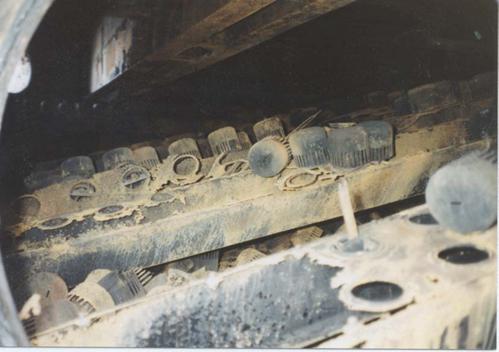
Severe NAC of 410 SS trays and bubble caps in the HVGO section of the vacuum tower fed by the vacuum heater
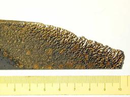
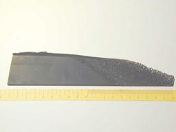
Examples of NAC
Corrosion of carbon steel can occur in plants using phenol as a solvent to remove aromatic compounds from lubricating oil feedstocks. Affected materials, in order of increasing resistance are : carbon steel, 304L, 316L and Alloy C276.
Temperature, water content, alloy chemistry and velocity are the critical factors. Corrosion is usually minimal in the treating section when the temperature is below 120°C. Corrosion can occur in the recovery section where spent phenol is separated by vaporization. Sulfur and organic acids may lead to naphthenic acid attack and sulfidation in the hot extract circuit. Carbon steel and 304/304L stainless steel corrode rapidly in phenol service above 230°C. Dilute aqueous solutions (5-15% phenol) are very corrosive to the extract dryer condensers. High velocities may promote localized corrosion.
Affected Units or Equipment
Phenol extraction facilities in lubes plant.
Appearance or Morphology of Damage
Corrosion will be in the form of general or localized corrosion of carbon steel. Localized loss in thickness due to erosion-corrosion may occur. Erosion-corrosion and/or condensation corrosion may be observed in tower overhead circuits.
Prevention / Mitigation
Corrosion is best prevented through proper materials selection and control of phenol solvent chemistry. Overhead piping circuits should be designed for a maximum velocity of 30 fps in the recovery section. Recovery tower overhead temperatures should be maintained to at least 15°C above the dew point. Type 316L stainless steel may be used in the top of the dry tower, phenol flash tower and various condenser shells and separator drums that handle phenol-containing water. Tubes and headers in extract furnaces should be 316L. ) Alloy C276 has been used in areas of high velocity or other locations where 316L is inadequate.
Inspection and Monitoring
UT and RT to monitor for loss in thickness. ER corrosion probes and corrosion coupons have been used for corrosion monitoring.
Phosphoric acid is most often used as a catalyst in polymerization units. It can cause both pitting corrosion and localized corrosion of carbon steels depending on water content. Affected materials are, in order of increasing resistance: carbon steel, 304L SS, 316L SS and Alloy 20.
Acid concentration, temperature and contaminants are critical factors. Solid phosphoric acid catalysts are not corrosive to carbon steel unless free water is present. When water is present, severe corrosion of carbon steel may occur. Corrosion rates increase with increasing temperature. Corrosion can penetrate a 1/4-inch thick steel tube in eight hours. Most corrosion probably occurs during water-washing operations at shutdowns. Contaminants, such as chlorides, can increase phosphoric acid corrosion.
Affected Units or Equipment
Piping and equipment in the polymerization unit where water mixes with catalyst. Corrosion is usually found in low velocity areas where there is little or no circulation such as piping manifolds, the bottom of kettle-type reboilers, partial penetration welds, and exchangers where there is sufficient residence time to permit the settling of acid droplets.
Appearance or Morphology of Damage
General or localized thinning of carbon steel.
Prevention / Mitigation
Selective upgrading to corrosion resistant materials is the only option where water cannot be eliminated. Type 304L SS is satisfactory for phosphoric acid concentration of 100% up to about 50°C. Type 316L SS is required from 50°C to 110°C. Type 316L SS and Alloy 20 are effective at concentrations up to 85% at boiling temperatures.
Inspection and Monitoring
UT and RT for loss of thickness. Sample iron in water from first column overhead receiver. Online corrosion monitoring using ER probes and/or corrosion coupons in the water draw from the first column overhead condenser and the reboiler.
Corrosion of steel due to acidic sour water containing H2S at a pH between 4.5 and 7.0. Carbon dioxide (CO2) may also be present. Sour waters containing significant amounts of ammonia, chlorides or cyanides may significantly affect pH but are outside the scope of this section. Affected materials are primarily affects carbon steel, whereas stainless steels, copper alloys and nickel base alloys are usually resistant.
H2S content, pH, temperature, velocity and oxygen concentration are all critical factors. The H2S concentration in the sour water is dependent on the H2S partial pressure in the gas phase as well as temperature and pH. At a given pressure, the H2S concentration in the sour water decreases as temperature increases. Increasing concentrations of H2S tend to decrease solution pH down to about 4.5. Streams with a pH below 4.5 indicate the presence of a strong acid which would be the main corrosion concern. Above a pH of about 4.5, a protective, thin iron sulfide layer limits the corrosion rate. In some instances at a pH above 4.5, a thicker, porous sulfide film layer can form. This can promote pitting under sulfide deposits. Typically, this does not affect the general corrosion rate. Other contaminants have a significant affect on water pH. For example, HCl and CO2 lower pH (more acidic). Ammonia significantly increases pH and is more often associated with alkaline sour water where the main concern is ammonia bisulfide corrosion. The presence of air or oxidants may increase the corrosion and usually produces pitting or underdeposit attacks.
Affected Units or Equipment
Acid sour water corrosion is a concern in overhead systems of FCC and coker gas fractionation plants with high H2S levels and low NH3 levels.
Appearance or Morphology of Damage
Corrosion damage from acidic sour water is typically general thinning. However, localized corrosion or localized underdeposit attack can occur, especially if oxygen is present. Corrosion in CO2 containing environments may be accompanied by carbonate stress corrosion cracking. 300 Series SS are susceptible to pitting attack and may experience crevice corrosion and/or chloride stress corrosion cracking.
Prevention / Mitigation
300 Series SS can be used at temperatures below about 60°C where Chloride Stress Corrosion Cracking (CSCC) is not likely. Copper alloys and nickel alloys are generally not susceptible to acid sour water corrosion. However, copper alloys are vulnerable to corrosion in environments with ammonia.
Inspection and Monitoring
Evidence of locally thinned areas can be found using scanning ultrasonic thickness methods or profile radiography. For carbon steel, damage is usually in the form general thinning but may be highly localized to specific areas of high velocity or turbulence, typically where a water phase is condensing. Process and corrosion monitoring are important aspects of a well-developed program to minimize the effects of acidic sour water corrosion. The water draws of overhead accumulators should be monitored periodically to measure pH. Properly placed corrosion probes and corrosion coupons provide additional information on the rate and extent of potential damage.
Sulfuric acid promotes general and localized corrosion of carbon steel and other alloys. Carbon steel heat affected zones may experience severe corrosion. Affected materials are, in order of increasing resistance: carbon steel, 316L SS, Alloy 20, high silicon cast iron, high nickel cast iron, Alloy B-2 and Alloy C276.
Critical factors are: acid concentration, temperature ,alloy content, velocity ,contamination and presence of oxidizers. Carbon steel corrosion rates increase significantly if the flow velocity exceeds about 2 to 3 fps (0.6 to 0.9 m/s) or at acid concentrations below 65%. Mix points with water cause heat to be released and high corrosion rates can occur where the acid becomes diluted. The presence of oxidizers can greatly increase the corrosion rate.
Affected Units or Equipment
Sulfuric acid alkylation units and waste water treatment plants are affected. Areas of vulnerability in sulfuric acid alkylation units include reactor effluent lines, reboilers, deisobutanizer overhead systems and the caustic treating section. Acid usually ends up in the bottom of fractionation towers and reboilers where it becomes concentrated.
Appearance or Morphology of Damage
Mostly general in nature, but attacks carbon steel weld heat affected zones rapidly. Hydrogen grooving may occur in low flow or stagnant areas such as in storage tanks or rail cars. Sulfuric acid attacks slag left from welding. If the corrosion rate and velocity are high, there will be no scale. Corrosion of steel by dilute acid is usually in the form of overall metal loss or pitting and becomes more severe with increasing temperature and velocity.
Prevention / Mitigation
Corrosion is minimized through materials selection and proper operation within design velocities. Alloys such as Alloy 20, Alloy 904L and Alloy C-276 resist dilute acid corrosion and form a protective iron sulfate film on the surface. Acidified product streams can be washed with caustic to neutralize the acid.
Inspection and Monitoring
UT or RT inspection of turbulent zones and hottest areas. Corrosion monitoring with coupons and ER probes.
Grooving corrosion in the carbon steel vapor line from an alkaline water wash drum in a sulfuric acid alkylation unit.
Environment-Assisted Cracking
A form of stress corrosion cracking normally occurring during shutdowns, startups or during operation when air and moisture are present. Cracking is due to sulfur acids forming from sulfide scale, air and moisture acting on sensitized austenitic stainless steels. Usually adjacent to welds or high stress areas. Cracking may propagate rapidly through the wall thickness of piping and components in a matter of minutes or hours. Affected materials are 300 Series SS, Alloy 600/600H and Alloy 800/800H.
A combination of environment, material, and stress are required.
i) Environment - Metallic components form a surface sulfide scale when exposed to sulfur compounds. The scale may react with air (oxygen) and moisture to form sulfur acids (polythionic acid).
ii) Material - The material must be in a susceptible or “sensitized” condition.
iii) Stress - Residual or applied.
Affected alloys become sensitized during exposure to elevated temperatures during manufacture, welding or high temperature service. “Sensitization” refers to the composition/time/temperature dependent formation of chromium carbide in the grain boundaries of the metal. Sensitization occurs in the 400°C to 820°C temperature range. The carbon content and the thermal history of the alloy have a significant effect on sensitization susceptibility. Regular and controlled carbon grades of stainless steels such as types 304/304H and 316/316H are particularly susceptible to sensitizing in the weld HAZ. Low carbon”L” grades (< 0.03% C) are less susceptible and usually can be welded without sensitizing. The L grades will not sensitize provided long term operating temperatures do not exceed about 400°C. Residual stresses in most components are usually sufficient to promote cracking.
Affected Units or Equipment
All units where sensitized alloys are used in sulfur-containing environments. Commonly damaged equipment includes heat exchanger tubes, furnace tubes and piping. Fired heaters burning oil, gas, coke and most other sources of fuel may be affected depending on sulfur levels in the fuel. Severe cases have been found in FCC units (air rings, plenums, slide valves, cyclone components, expansion joint bellows and piping). In hydroprocessing units (heater tubes, hot feed/effluent exchanger tubes, bellows). Crude and coker units (piping). Boilers and high temperature equipment exposed to sulfur-containing combustion products.
Appearance or Morphology of Damage
Typically occurs next to welds, but can also occur in the base metal. It is usually quite localized and may not be evident until a leak appears during start-up or, in some cases, operation. Cracking propagates intergranularly. Corrosion or loss in thickness is usually negligible.
Prevention / Mitigation
If equipment will be opened or exposed to air, preventive measures should be taken to minimize or eliminate PASCC include flushing the equipment with alkaline or soda ash solution to neutralize sulfur acids immediately after or during shutdown or purging with dry nitrogen or nitrogen/ammonia during the shutdown to prevent air exposure. Refer to guidelines in NACE RP0170. For furnaces, keep the firebox heated above the dewpoint to prevent acids from forming on heater tubes. Low carbon grades such as 304L/316L/317L provide some measure of improvement over controlled carbon grades. The L grades will sensitize if exposed more than several hours above about 540°C or long term above 400°C. Improved resistance to PASCC cracking can be achieved with modified versions of these alloys containing small amounts of Ti and Nb. Typically used are the chemically stabilized grades (austenitic stainless steel types 321 and 347 and nickel base Alloys 825 and 625). ASTM specifications allow mill products to be shipped in a stabilized condition rather than solution annealed. This heat treatment will minimize potential sensitization problems especially with type 321. A thermal stabilization heat treatment at 900°C may be applied to chemically stabilized austenitic stainless steel welds after all welding is complete in an attempt to reduce sensitization and PTA susceptibility. This heat treatment is difficult to apply in the field. Susceptibility to PASCC can be determined by laboratory corrosion testing according to ASTM A262 Practice C. A sensitizing heat treatment is often applied to L and/or chemically stabilized grades prior to testing.
Inspection and Monitoring
PT examination can be used to detect PASCC cracking. However, because the cracks are filled with a tight deposit, flapper disc sanding may be needed to improve the PT sensitivity. PASCC cracking can be an inspection challenge because the cracking may not occur until well into a turnaround. Monitoring for PASCC cracking during operation is not usually practical. Conditions causing the cracking are not usually present while operating.
Dye penetrant inspection showing extensive O.D. cracking around welds.
Amine cracking is a common term applied to the cracking of steels under the combined action of tensile stress and corrosion in aqueous alkanolamine systems used to remove/absorb H2S and/or CO2 and their mixtures from various gas and liquid hydrocarbon streams. Amine cracking is a form of alkaline stress corrosion cracking. It is most often found at or adjacent to non-PWHT’d carbon steel weldments or in highly cold worked parts. Amine cracking should not be confused with several other types of SCC that can occur in amine environments. Affected materials are carbon steel and low alloy steels.
The critical factors are the level of tensile stress, amine concentration and temperature. Cracking is associated with residual stresses from welding, cold working or fabrication that have not been removed through an effective stress-relieving heat treatment. Cracking is more likely to occur in lean MEA and DEA services but is also found in most amines including MDEA and DIPA (ADIP). Cracking has been reported down to ambient temperatures with some amines. Increasing temperature and stress levels increases the likelihood and severity of cracking. Refer to API RP 945 for guidelines on PWHT requirements for various amine services. Amine cracking is most often associated with lean amine services. The pure alkanolamine does not cause cracking. Cracking in rich amine services are most often associated with wet H2S problems. Cracking can occur in non-PWHT’d piping and equipment as a result exposure to steamout and to short-term amine carryover. Amine concentration does not appear to have a significant effect on the propensity for cracking. Some refiners believe cracking will not occur below an amine concentration of about 2% to 5%. However, local enrichment and steamout can reduce this limit and some plants have used lower limits down to 0.2%.
Affected Units or Equipment
All non-PWHT carbon steel piping and equipment in lean amine service including contactors, absorbers, strippers, regenerators and heat exchangers as well as any equipment subject to amine carryover.
Appearance or Morphology of Damage
Amine cracking results in surface breaking flaws that initiate on the ID of piping and equipment primarily in the weld HAZ but has also been found in weld metal and high stress areas adjacent to the HAZ. Cracking typically develops parallel to the weld and there may be parallel cracks. In weld metal, the cracks are either transverse or longitudinal with the weld. At set-on nozzles, the cracks are radial in the base metal, i.e., they fan out from the bore. At set-in nozzles, the cracks are usually parallel to the weld. The appearance of the cracks on the surface may be similar to those caused by wet H2S cracking. Since the driving force for cracking is residual stress, cracks are often found on the process side, opposite external attachment welds. Positive identification of amine cracking can be confirmed by metallographic analysis. The cracking is typically intergranular, oxide filled with some branching.
Prevention / Mitigation
PWHT all carbon steel welds in piping and equipment in accordance with API RP 945. The same requirement applies to repair welds and to internal and external attachment welds. Use solid or clad stainless steel, Alloy 400 or other corrosion resistant alloys in lieu of carbon steel. Water wash non-PWHT carbon steel piping and equipment prior to welding, heat treatment or steamout.
Inspection and Monitoring
Although cracks may be seen visually, crack detection is best performed with WFMT or ACFM techniques. Surface preparation by grit blasting, high pressure water blasting or other methods is required for WFMT but may not be necessary for ACFM. PT is usually not effective in finding tight and/or scale filled cracks and should not be used. If the cracks have minimum branching, crack depths can be measured with a suitable UT technique including external SWUT. AET can also be used for monitoring crack growth and locating growing cracks.
A photomicrograph of a cross-section of a weld in non-PWHT piping showing a SCC in the vicinity of a piping weld. Mag. 6x (From API 945)
This section describes four types of damage that result in blistering and/or cracking of carbon steel and low alloy steels in wet H2S environments.
Hydrogen Blistering
Hydrogen blisters may form as surface bulges on the ID, the OD or within the wall thickness of a pipe or pressure vessel. The blister results from hydrogen atoms that form during the sulfide corrosion process on the surface of the steel, that diffuse into the steel, and collect at a discontinuity in the steel such as an inclusion or lamination. The hydrogen atoms combine to form hydrogen molecules that are too large to diffuse out and the pressure builds to the point where local deformation occurs, forming a blister. Blistering results from hydrogen generated by corrosion, not hydrogen gas from the process stream.
Hydrogen Induced Cracking (HIC)
Hydrogen blisters can form at many different depths from the surface of the steel, in the middle of the plate or near a weld. In some cases, neighboring or adjacent blisters that are at slightly different depths (planes) may develop cracks that link them together. Interconnecting cracks between the blisters often have a stair step appearance, and so HIC is sometimes referred to as “stepwise cracking”.
Stress Oriented Hydrogen Induced Cracking (SOHIC)
SOHIC is similar to HIC but is a potentially more damaging form of cracking which appears as arrays of cracks stacked on top of each other. The result is a through-thickness crack that is perpendicular to the surface and is driven by high levels of stress (residual or applied). They usually appear in the base metal adjacent to the weld heat affected zones where they initiate from HIC damage or other cracks or defects including sulfide stress cracks.
Sulfide Stress Corrosion Cracking (SSC)
Sulfide Stress Cracking (SSC) is defined as cracking of metal under the combined action of tensile stress and corrosion in the presence of water and H2S. SSC is a form of hydrogen stress cracking resulting from absorption of atomic hydrogen that is produced by the sulfide corrosion process on the metal surface. SSC can initiate on the surface of steels in highly localized zones of high hardness in the weld metal and heat affected zones. Zones of high hardness can sometimes be found in weld cover passes and attachment welds which are not tempered (softened) by subsequent passes. PWHT is beneficial in reducing the hardness and residual stresses that render a steel susceptible to SSC. High strength steels are also susceptible to SSC but these are only used in limited applications in the refining industry. Some carbon steels contain residual elements that form hard areas in the heat affected zones that will not temper at normal stress relieving temperatures. Using preheat helps minimize these hardness problems.
Affected materials are carbon steel and low alloy steels.
The most important variables that affect and differentiate the various forms of wet H2S damage are environmental conditions (pH, H2S level, contaminants, temperature), material properties (hardness, microstructure, strength) and tensile stress level (applied or residual). These factors are outlined below. All of these damage mechanisms are related to the absorption and permeation of hydrogen in steels.
• pH
§ Hydrogen permeation or diffusion rates have been found to be minimal at pH 7 and increase at both higher and lower pH’s. The presence of hydrogen cyanide (HCN) in the water phase significantly increases permeation in alkaline (high pH) sour water.
§ Conditions which are known to promote blistering, HIC, SOHIC and SSC are those containing free water (in liquid phase) and:
· >50 wppm dissolved H2S in the free water, or
· free water with pH <4 and some dissolved H2S present, or
· free water with pH >7.6 and 20 wppm dissolved hydrogen cyanide (HCN) in the water and some dissolved H2S present, or
· >0.0003 MPa (0.05 psia) partial pressure of H2S in the gas phase.
§ Increasing levels of ammonia may push the pH higher into the range where cracking can occur.
• H2S
§ Hydrogen permeation increases with increasing H2S partial pressure due to a concurrent increase in the H2S concentration in the water phase.
§ An arbitrary value of 50 wppm H2S in the water phase is often used as the defining concentration where wet H2S damage becomes a problem. However, there are cases where cracking has occurred at lower concentrations or during upset conditions where wet H2S was not ordinarily anticipated. The presence of as little as 1 wppm of H2S in the water has been found to be sufficient to cause hydrogen charging of the steel.
§ Susceptibility to SSC increases with increasing H2S partial pressures above about 0.05 psi (0.0003 MPa) H2S in steels with a tensile strength above about 90 ksi or in steels with localized zones of weld or weld HAZ hardness above 237 HB.
• Temperature
§ Blistering, HIC, and SOHIC damage have been found to occur between ambient and 150°C or higher.
§ SSC generally occurs below about 80°C.
• Hardness
§ Hardness is primarily an issue with SSC. Typical low-strength carbon steels used in refinery applications should be controlled to produce weld hardness <200 HB in accordance with NACE RP0472. These steels are not generally susceptible to SSC unless localized zones of hardness above 237 HB are present.
§ Blistering, HIC and SOHIC damage are not related to steel hardness.
• Steelmaking
§ Blistering and HIC damage are strongly affected by the presence of inclusions and laminations which provide sites for diffusing hydrogen to accumulate.
§ Steel chemistry and manufacturing methods also affect susceptibility and can be tailored to produce the HIC resistant steels outlined in NACE Publication 8X194.
§ Improving steel cleanliness and processing to minimize blistering and HIC damage may still leave the steel susceptible to SOHIC.
§ The disadvantage is that an absence of visual blistering may leave a false sense of security that H2S damage is not active yet subsurface SOHIC damage may be present.
§ HIC is often found in so-called “dirty” steels with high levels of inclusions or other internal discontinuities from the steel-making process.
• PWHT
§ Blistering and HIC damage develop without applied or residual stress so that PWHT will not prevent them from occuring.
§ High local stresses or notch-like discontinuities such as shallow sulfide stress cracks can serve as initiation sites for SOHIC. PWHT is highly effective in preventing or eliminating SSC by reduction of both hardness and residual stress.
§ SOHIC is driven by localized stresses so that PWHT is also somewhat effective in reducing SOHIC damage.
Affected Units or Equipment
Blistering, HIC, SOHIC and SSC damage can occur throughout the refinery wherever there is a wet H2S environment present. In hydroprocessing units, increasing concentration of ammonium bisulfide above 2% increases the potential for blistering, HIC and SOHIC. Cyanides significantly increase the probability and severity of blistering, HIC and SOHIC damage. This is especially true for the vapor recovery sections of the fluid catalytic cracking and delayed coking units. Typical locations include fractionator overhead drums, fractionation towers, absorber and stripper towers, compressor interstage separators and knockout drums and various heat exchangers, condensers, and coolers. Sour water stripper and amine regenerator overhead systems are especially prone to wet H2S damage because of generally high ammonia bisulfide concentrations and cyanides. SSC is most likely found in hard weld and heat affected zones and in high strength components including bolts, relief valve springs, 400 Series SS valve trim, compressor shafts, sleeves and springs.
Appearance or Morphology of Damage
All four forms of wet H2S damage are best illustrated though the pictures and diagrams. Hydrogen blisters appear as bulges on the ID or OD surface of the steel and can be found anywhere in the shell plate or head of a pressure vessel. Blistering has been found on rare occasions in pipe and very rarely in the middle of a weld. HIC damage can occur wherever blistering or subsurface laminations are present. In pressure-containing equipment, SOHIC and SSC damage is most often associated with the weldments. SSC can also be found at any location where zones of high hardness are found in vessels or in high strength steel components.
Prevention / Mitigation
Effective barriers that protect the surface of the steel from the wet H2S environment can prevent damage including alloy cladding and coatings. Process changes that affect the pH of the water phase and/or ammonia or cyanide concentration can help to reduce damage. A common practice is to utilize wash water injection to dilute the HCN concentration, for example, in FCC gas plants. Cyanides can be converted to harmless thiocyanates by injecting dilute streams of ammonium polysulfides. Injection facilities require careful design. HIC-resistant steels can be used to minimize the susceptibility to blistering and HIC damage. Detailed materials and fabrication guidance can be found in NACE Publication 8X194. SSC can generally be prevented by limiting the hardness of welds and heat affected zones to 200 HB maximum through preheat, PWHT, weld procedures and control of carbon equivalents. Depending on the service environment, small zones of hardness up to 22 HRC should be resistant to SSC. Refer to NACE RP0472 for additional details.
PWHT can also help to minimize susceptibility to SOHIC. PWHT has limited value in preventing blistering and HIC damage from initiating but is beneficial in reducing residual stresses and strength levels that might otherwise contribute to crack propagation. Specialized corrosion inhibitors can be used.
Inspection and Monitoring
Process conditions should be evaluated by process engineers and corrosion/materials specialists to identify piping and equipment where conditions are most likely to promote wet H2S damage. Field sampling of the free water phase should be performed on a periodic or as-needed basis to monitor conditions or changes in conditions, particularly if water washing or polysulfide injection is used. Inspection for wet H2S damage generally focuses on weld seams and nozzles. Since the consequences can be severe, refineries generally have a procedure to prioritize and execute inspection for this type of damage. General notes on inspection for wet H2S damage are included below. However, for the development of more detailed inspection plans including methods, coverage and surface preparation, the reader is directed to extensive recommendations on detection and repair outlined in NACE RP0296. Although cracks may be seen visually, crack detection is best performed with WFMT, EC, RT or ACFM techniques. Surface preparation by grit blasting, high pressure water blasting or other methods is usually required for WFMT but not for ACFM. PT cannot find tight cracks and should not be depended on. UT techniques including external SWUT can be used. SWUT is especially useful for volumetric inspection and crack sizing. Electrical resistance instruments are not effective for measuring crack depth. Grinding out the crack or removal by thermal arc gouging is a viable method of crack depth determination. AET can be used for monitoring crack growth.
Extensive hydrogen blistering on the surface of steel pressure vessel.
High magnification photomicrograph of HIC damage.
High magnification photomicrograph showing stepwise cracking nature of HIC damage.
Hydrogen Stress Cracking is a form of environmental cracking that can initiate on the surface of high strength low alloy steels and carbon steels with highly localized zones of high hardness in the weld metal and HAZ as a result of exposure to aqueous HF acid environments. Affected materials are carbon steel and low alloy steels.
Steel hardness, strength and stress are the critical factors. Susceptibility increases with increasing hardness. Hardness levels above Rockwell C 22 (237 BHN) are highly susceptible. Time-to-failure decreases as the hardness increases (higher strength materials). Under high levels of applied or residual tensile stress (from cold-forming or welding) embrittlement results in cracking of susceptible steels. Cracking may occur very rapidly, within hours after exposure to the HF environment, or considerable time may pass before cracking initiates. Hard microstructures may arise in welds, particularly in low heat input welds in the heat affected zones, in low alloy steels, or may result from inadequate heat treatment.
Affected Units or Equipment
All piping and equipment exposed to HF acid at any concentration with hardness levels above the recommended limit are subject to hydrogen stress cracking. High strength low alloy steels such as ASTM A193-B7 bolts and compressor components are susceptible. ASTM A193B7M bolts are also susceptible if overtorqued.
Appearance or Morphology of Damage
This mode of cracking can only be confirmed by metallographic examination. The cracking will be intergranular. Produces surface breaking cracks, usually associated with weldments.
Prevention / Mitigation
PWHT is beneficial in reducing the hardness and residual stresses that render a steel susceptible to SSC. Typical low-strength carbon steels used in refinery applications should be controlled to produce weld hardness <200 HB in accordance with NACE RP0472. These steels are not generally susceptible to SCC unless localized zones of hardness above 237 HB are present. Use carbon steels with Carbon Equivalents (CE) less than 0.43. Where CE is defined as:
CE = %C + %Mn/6+ %(Cr + Mo + V)/5 + %(Cu + Ni)/15
ASTM A193 grade B7M bolts are softer and lower strength than B7 bolts and are more resistant to cracking. Alloy cladding or nonmetallic coatings that provide an effective barrier and protect the surface of the steel from hydrogen permeation will prevent cracking. Alloy 400 is not susceptible to this form of cracking but may be susceptible to intergranular stress corrosion cracking, particularly in the non-stress relieved condition.
Inspection and Monitoring
Surface breaking cracks can be found by WFMT. Hardness testing is the best method to determine the susceptibility of suspect material. Zones of high hardness can sometimes be found on the process side in weld cover passes and attachment welds that are not tempered (softened) by subsequent passes.
Carbonate stress corrosion cracking (often referred to as carbonate cracking) is the term applied to surface breaking or cracks that occur adjacent to carbon steel welds under the combined action of tensile stress and corrosion in carbonate-containing systems. It is a form of Alkaline Stress Corrosion Cracking (ASCC). Affected materials are carbon steel and low alloy steels.
Stress level and water chemistry are the critical factors. Carbonate stress corrosion cracking can occur at relatively low levels of residual stress but usually occurs at welds or cold worked areas that have not been stress relieved. Cracking susceptibility increases with increasing pH and carbonate (CO3 -2) concentration. It can occur under the following conditions:
• Non-stress relieved carbon steel,
• pH > 9.0 and CO3 -2 > 100 ppm, or
• 8
<9.0 and CO3 -2 > 400 ppm.
If the equipment/piping contains a water phase with 50 wppm or greater H2S at a pH of 7.6 or greater, the equipment/piping is considered susceptible. Cyanides have also been shown to increase cracking susceptibility. In gas scrubbing units, cracking may occur when the CO2 content is above 2% and temperatures exceed 90°C.
Affected Units or Equipment
Carbonate cracking has been most prevalent in the fluid catalytic cracking unit main fractionators overhead condensing and reflux system, the downstream wet gas compression system, and the sour water systems emanating from these areas. Both piping and vessels are affected. Carbonate cracking has also occurred in piping and equipment in potassium carbonate, Catacarb and CO2 removal facilities of hydrogen manufacturing units.
Appearance or Morphology of Damage
Carbonate cracking typically propagates parallel to the weld in the adjacent base metal, but can also occur in the weld deposit or heat-affected zones. The pattern of cracking observed on the steel surface is sometimes described as a spider web of small cracks, which often initiate at or interconnect with weld-related flaws that serve as local stress raisers. These cracks may be easily mistaken for SSC or SOHIC, however, the carbonate cracks are usually further from the toe of the weld and have multiple parallel cracks. Carbonate cracks are surface breaking flaws that are predominantly intergranular in nature and typically occur in as-welded carbon steel fabrications as a network of very fine, oxide-filled cracks.
Prevention / Mitigation
Application of a post-fabrication stress-relieving heat treatment of about 620° is a proven method of preventing carbonate cracking. Heat treatment requirements apply to repair welds as well as internal and external attachment welds. Cracking can be eliminated through the use of effective barrier coatings, solid or clad 300 Series SS, Alloy 400 or other corrosion resistant alloys in lieu of carbon steel. Water wash non-PWHT piping and equipment prior to steamout or heat treatment in hot carbonate systems. A metavanadate inhibitor can be used in hot carbonate systems in CO2 removal units in hydrogen manufacturing units to prevent cracking. Proper dosing and oxidation of the inhibitor must be maintained.
Inspection and Monitoring
The cracking can involve sporadic and rapid growth, depending on subtle changes in the process, so monitoring has not typically been done. However, periodic monitoring of pH and CO3 -2 concentration in FCC sour waters should be done to determine cracking susceptibility. Although cracks may be seen visually, crack detection is best performed with WFMT or ACFM techniques. Surface preparation by grit blasting, high pressure water blasting or other methods is usually required for WFMT. PT usually cannot find tight or scale filled cracks and should not be used. There is usually much branching so crack depths may be measured with a suitable UT technique including external SWUT. Electrical resistance type instruments that measure crack depth are not effective because the cracks typically contain magnetic iron oxide. This cracking is not susceptible to extension by grinding. Grinding out the cracks is a viable method of crack depth determination. AET can be used for monitoring crack growth and locating growing cracks.
Carbonate cracking at and adjacent to the weldment in a non-PWHT piping weld in an FCC gas plant after 15 years service
Photomicrograph of a cross-section of carbonate cracking in the base metal, showing the branched nature of the cracking.
Other Mechanisms
High temperature hydrogen attack results from exposure to hydrogen at elevated temperatures and pressures. The hydrogen reacts with carbides in steel to form methane (CH4) which cannot diffuse through the steel. The loss of carbide causes an overall loss in strength. Methane pressure builds up, forming bubbles or cavities, microfissures and fissures that may combine to form cracks. Failure can occur when the cracks reduce the load carrying ability of the pressure containing part. Affected materials are, in order of increasing resistance: carbon steel, C-0.5Mo, Mn-0.5Mo, 1Cr-0.5Mo, 1.25Cr-0.5Mo, 2.25Cr-1Mo, 2.25Cr-1Mo-V, 3Cr-1Mo, 5Cr-0.5Mo and similar steels with variations in chemistry.
For a specific material, HTHA is dependent on temperature, hydrogen partial pressure, time and stress. Service exposure time is cumulative. HTHA is preceded by a period of time when no noticeable change in properties is detectable by normal inspection techniques. The incubation period is the time period during which enough damage has occurred to be measured with available inspection techniques and may vary from hours at very severe conditions to many years. Figure 80 contains curves that show a temperature/hydrogen partial pressure safe operating envelope for carbon and low alloy steels. Additional information on HTHA can be found in API RP 941. The curves are reasonably conservative for carbon steel up to about 10,000 psi hydrogen partial pressure. 300 Series SS, as well as 5Cr, 9Cr and 12 Cr alloys, are not susceptible to HTHA at conditions normally seen in refinery units.
Affected Units
Hydroprocessing units, such as hydrotreaters (desulfurizers) and hydrocrackers, catalytic reformers, hydrogen producing units and hydrogen cleanup units, such as pressure swing absorption units, are all susceptible to HTHA. Boiler tubes in very high pressure steam service.
Appearance or Morphology of Damage
HTHA can be confirmed through the use of specialized techniques including metallographic analysis of damaged areas as described below. The hydrogen/carbon reaction can cause surface decarburization of steel. If the diffusion of carbon to the surface is limiting, the reaction can result in internal decarburization, methane formation and cracking. In the early stages of HTHA, bubbles/cavities can be detected in samples by a scanning microscope, although it may be difficult to tell the difference between HTHA cavities and creep cavities. Some refinery services expose low alloy steels to both HTHA and creep conditions. Early stages of HTHA can only be confirmed through advanced metallographic analysis of damaged areas.In later stages of damage, decarburization and/or fissures can be seen by examining samples under a microscope and may sometimes be seen by in-situ metallography. Cracking and fissuring are intergranular and occur adjacent to pearlite (iron carbide) areas in carbon steels. Some blistering may be visible to the naked eye, due to either molecular hydrogen or methane accumulating in laminations in the steel.
Prevention/Mitigation
Use alloy steels with chromium and molybdenum to increase carbide stability thereby minimizing methane formation. Other carbide stabilizing elements include tungsten and vanadium. Normal design practice is to use a 14°C to 28°C safety factor approach when using the API RP 941 curves. While the curves have served the industry well, there have been several failures of C-0.5Mo steels in refinery service under conditions that were previously considered safe. C-0.5Mo carbide stability under HTHA conditions may be due at least in part to the different carbides formed during the various heat treatments applied to the fabricated equipment. As a result of the problems with the 0.5 Mo alloy steels, its curve has been removed from the main set of curves and the material is not recommended for new construction in hot hydrogen services. For existing equipment, this concern has prompted an economic review of inspection cost versus replacement with a more suitable alloy. Inspection is very difficult because problems have occurred in weld heat affected zones as well as base metal away from welds. 300 Series SS overlay and/or roll bond clad material is used in hydrogen service where the base metal does not have adequate sulfidation resistance. Although it is recognized that properly metallurgically bonded austenitic overlay/clad will decrease the hydrogen partial pressure seen by the underlying metal, most refiners make sure the base metal has adequate resistance to HTHA under service conditions. In some cases, refiners take the decrease in partial pressure into account when evaluating the need for hydrogen outgassing while shutting down heavy wall equipment.
Inspection and Monitoring
Damage may occur randomly in welds or weld heat affected zones as well as the base metal, making monitoring and detection of HTHA in susceptible materials extremely difficult. Ultrasonic techniques using a combination of velocity ratio and backscatter have been the most successful in finding fissuring and/or serious cracking. In-situ metallography can only detect microfissuring, fissuring and decarburization near the surface. However, most equipment has decarburized surfaces due to the various heat treatments used during fabrication. Visual inspection for blisters on the inside surface may indicate methane formation and potential HTHA. However, HTHA may frequently occur without the formation of surface blisters. Other conventional forms of inspection, including WFMT and RT, are severely limited in their ability to detect anything except the advanced stages of damage where cracking has already developed. AET is not a proven method for the detection of damage.
Recommended pressure and H2 partial pressure limits per API 941
High magnification photomicrograph showing linkup of microfissures to form continuous cracks. Note that damage is accompanied by a significant amount of decarburization.
Hydriding of titanium is a metallurgical phenomenon in which hydrogen diffuses into the titanium and reacts to form an embrittling hydride phase. This can result in a complete loss of ductility with no noticeable sign of corrosion or loss in thickness. Affected materials are titanium alloys.
The critical factors are metal temperature, solution chemistry and alloy composition. This is a phenomenon that occurs in specific environments at temperatures above 75°C and at a pH below 3, pH above 8 or neutral pH with high H2S content. Galvanic contact between titanium and more active materials such as carbon steel and 300 Series SS promotes damage. However, hydriding can occur in the absence of a galvanic coupling. Embrittlement occurs over a period of time as hydrogen is absorbed by the component and reacts to form embrittling hydride phases. The depth and extent of hydriding will continue to increase until a complete loss of ductility results. Hydriding has also occurred in some chemical environments as a result of the corrosion of iron which has been accidentally embedded into the surface of titanium during fabrication. Corrosion of iron and iron sulfide scale in the process streams brought in from upstream units can result in hydrogen pickup. The solubility of hydrogen in pure titanium and alpha-beta alloys is limited (50 - 300 ppm) and once this is exceeded, hydride is formed. Beta alloys, on the other hand, are more tolerant of hydrogen and 2000 ppm can be tolerated.
Affected Units or Equipment
Damage has occurred primarily in sour water strippers and amine units in the overhead condensers, heat exchanger tubes, piping and other titanium equipment operating above about 75°C. Hydriding can also occur in hydrogen atmospheres at temperatures >180°C, especially in the absence of moisture or oxygen. Cathodically protected equipment with protection potentials <-0.9 v sce.
Appearance or Morphology of Damage
Titanium hydriding is a metallurgical change that is not readily apparent, and can only be confirmed through metallurgical techniques or mechanical testing. A quick test for embrittlement is a bend test or a crush test in a vice. Unaffected titanium will be crushed in a ductile fashion while embrittled components will crack and/or shatter with little or no sign of ductility. Heat exchanger tubes that have become embrittled may remain intact until disturbed by removal of the bundle for inspection. The tubes crack as the bundle flexes when it is removed. Cracking can occur if there is an attempt to re-roll tube ends that have become embrittled. Another possible damage mode that has occurred is ignition and fire of titanium tubes. Metallographic examination of titanium tubes from a bundle that burned showed significant amounts of hydride, especially in the vicinity of the metal that had been melted.
Prevention / Mitigation
Titanium should not be used in known hydriding services such as amine or sour water, where the possibility of a leak is not acceptable.
Where galvanic contact has promoted hydriding, the problem can be avoided by using all titanium construction or by electrically isolating the titanium from non-titanium components. Eliminating the galvanic couple may not prevent hydriding in alkaline sour water environments.
Inspection and Monitoring
Specialized eddy current techniques are reported to have been able to detect hydriding damage. There are no other techniques to monitor or inspect for titanium hydriding other than the metallurgical and/or mechanical methods mentioned above.
Titanium heat exchanger tube that failed from hydriding in a sour water cooler. The cooling medium is sea water.
Interactive Typical Refinery Units
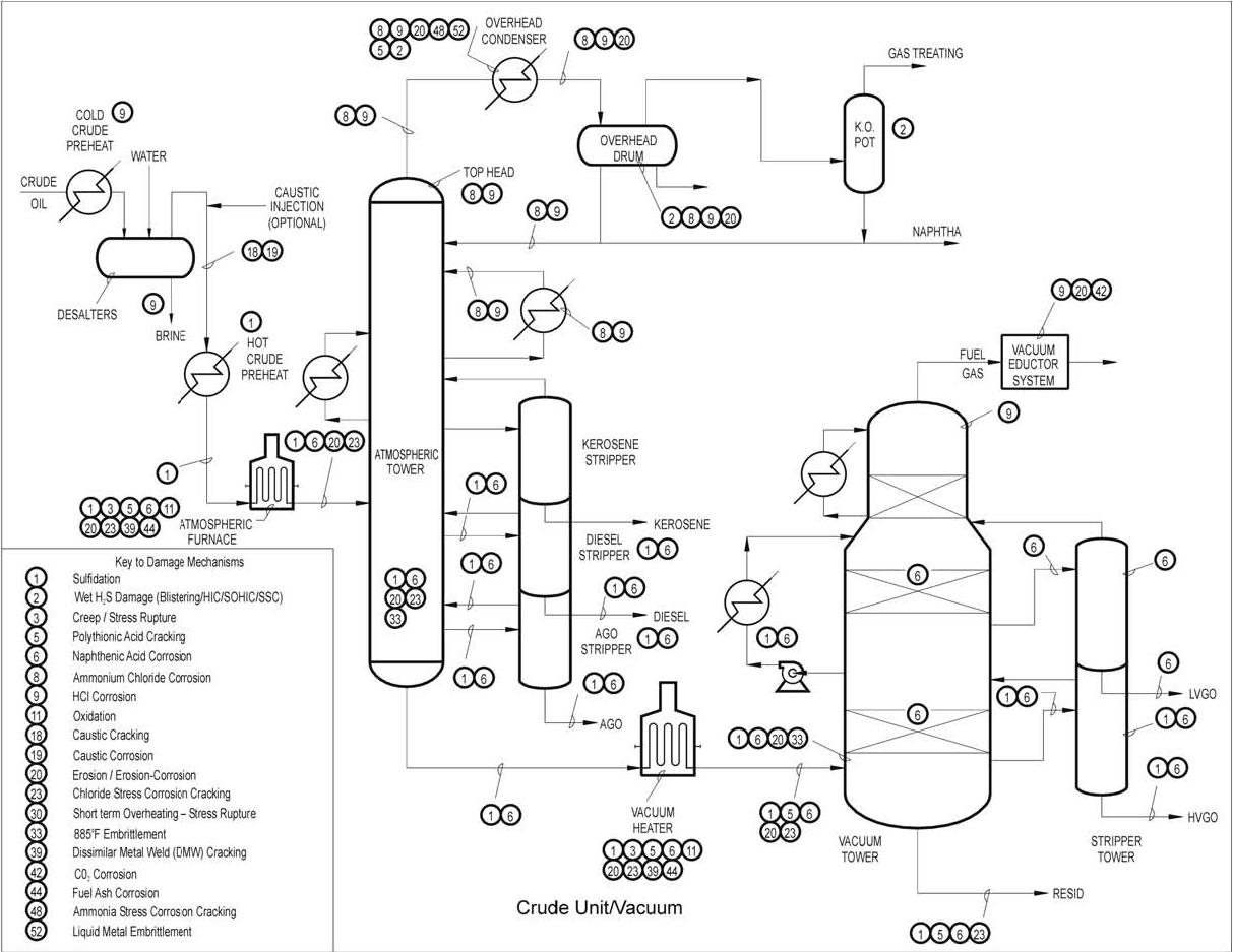
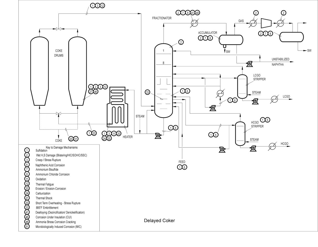
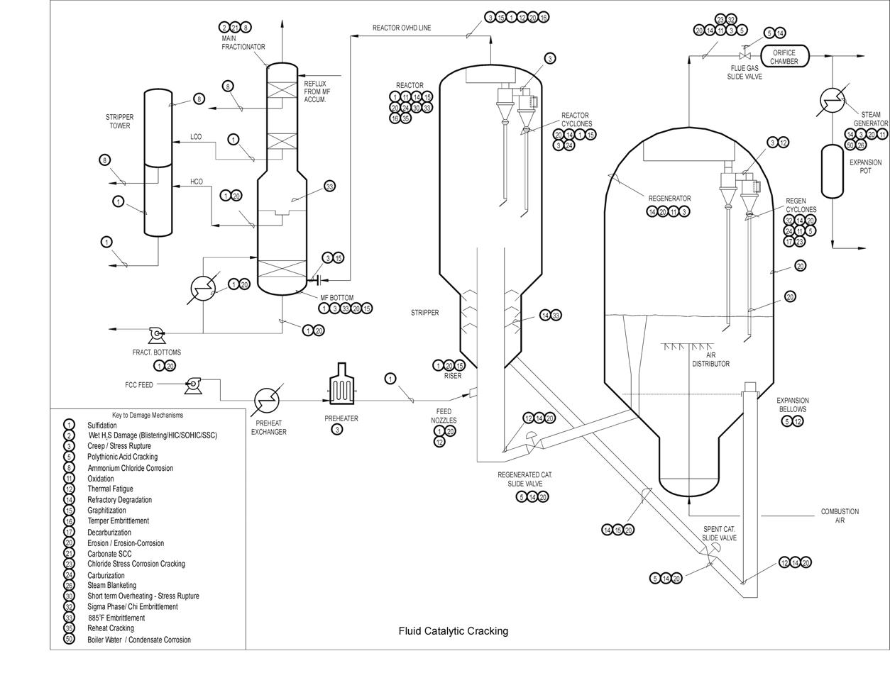
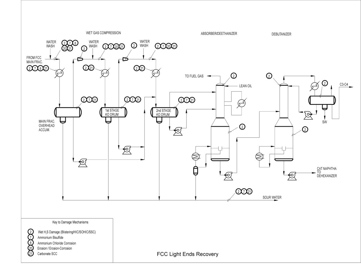
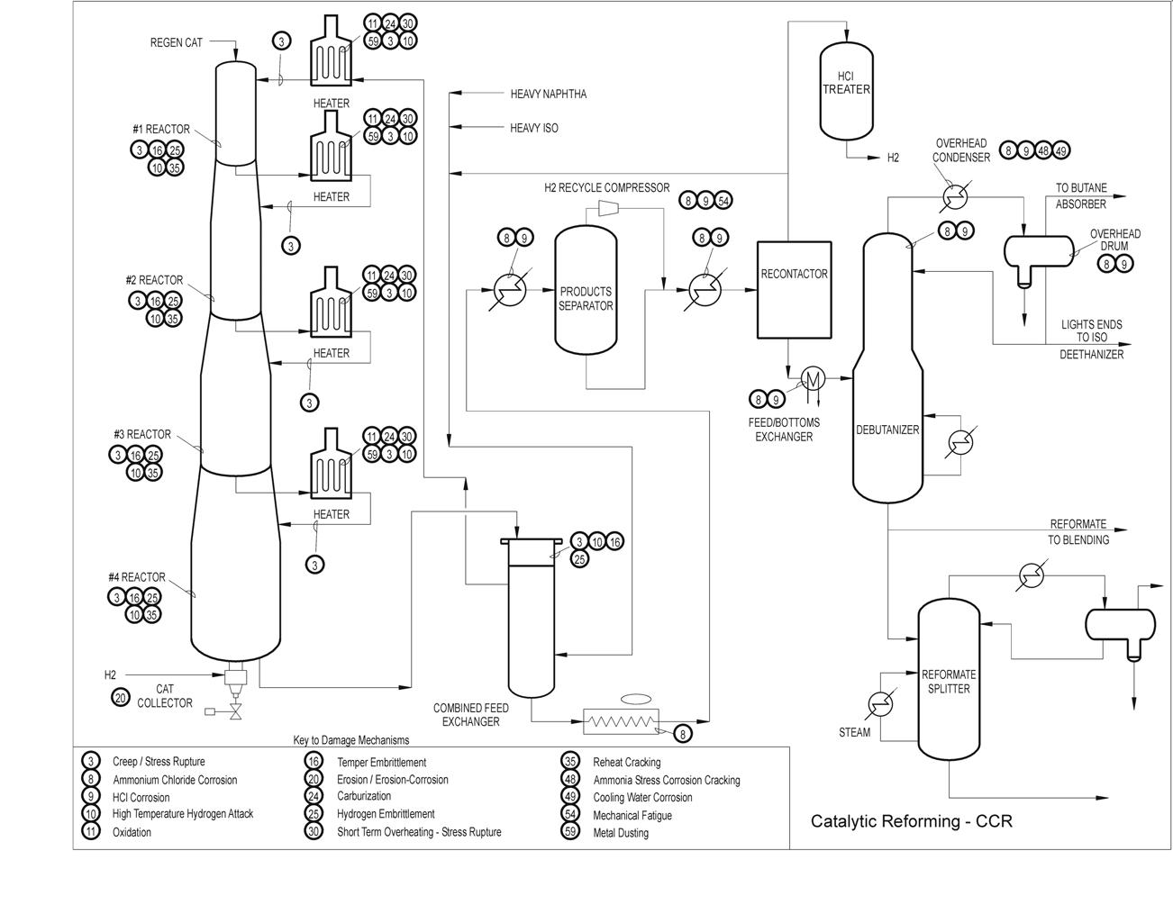
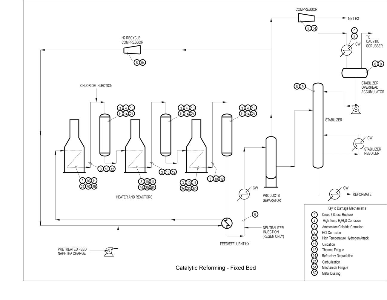
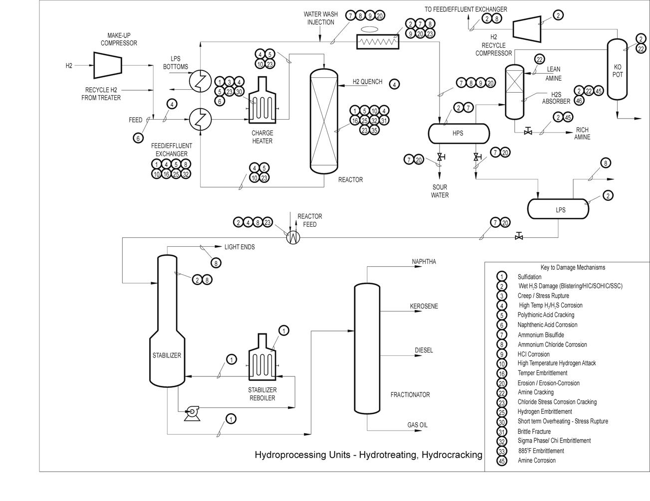
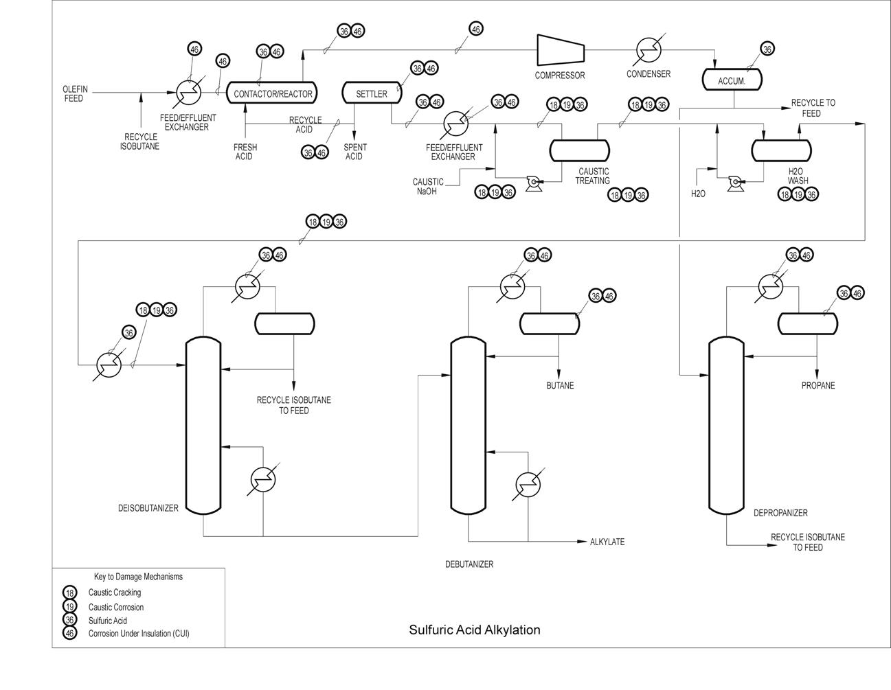
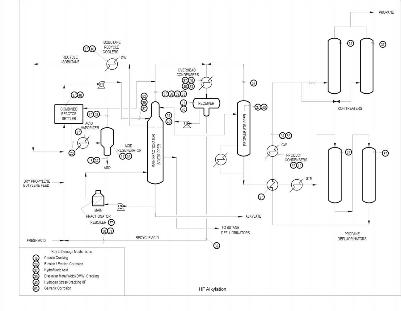
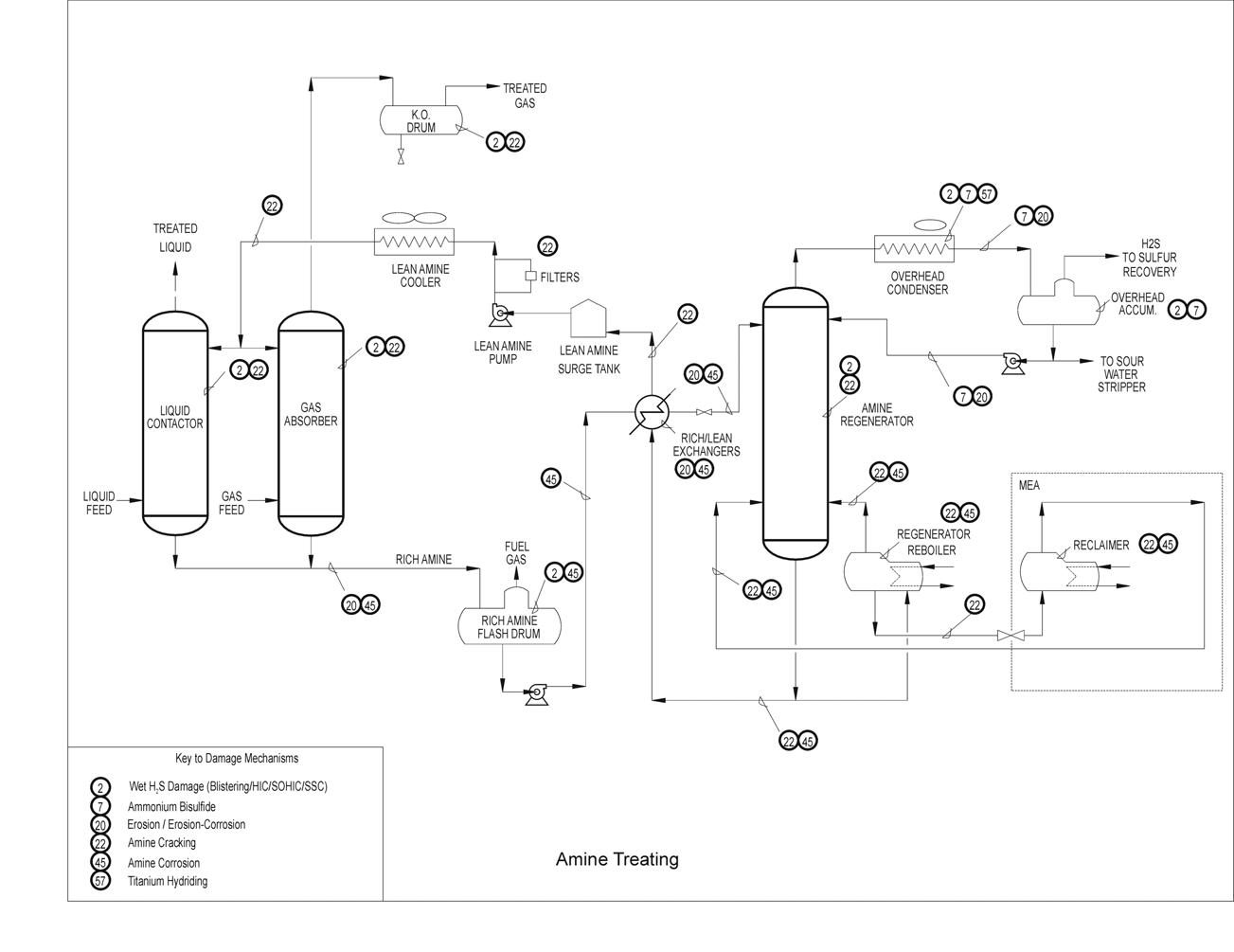
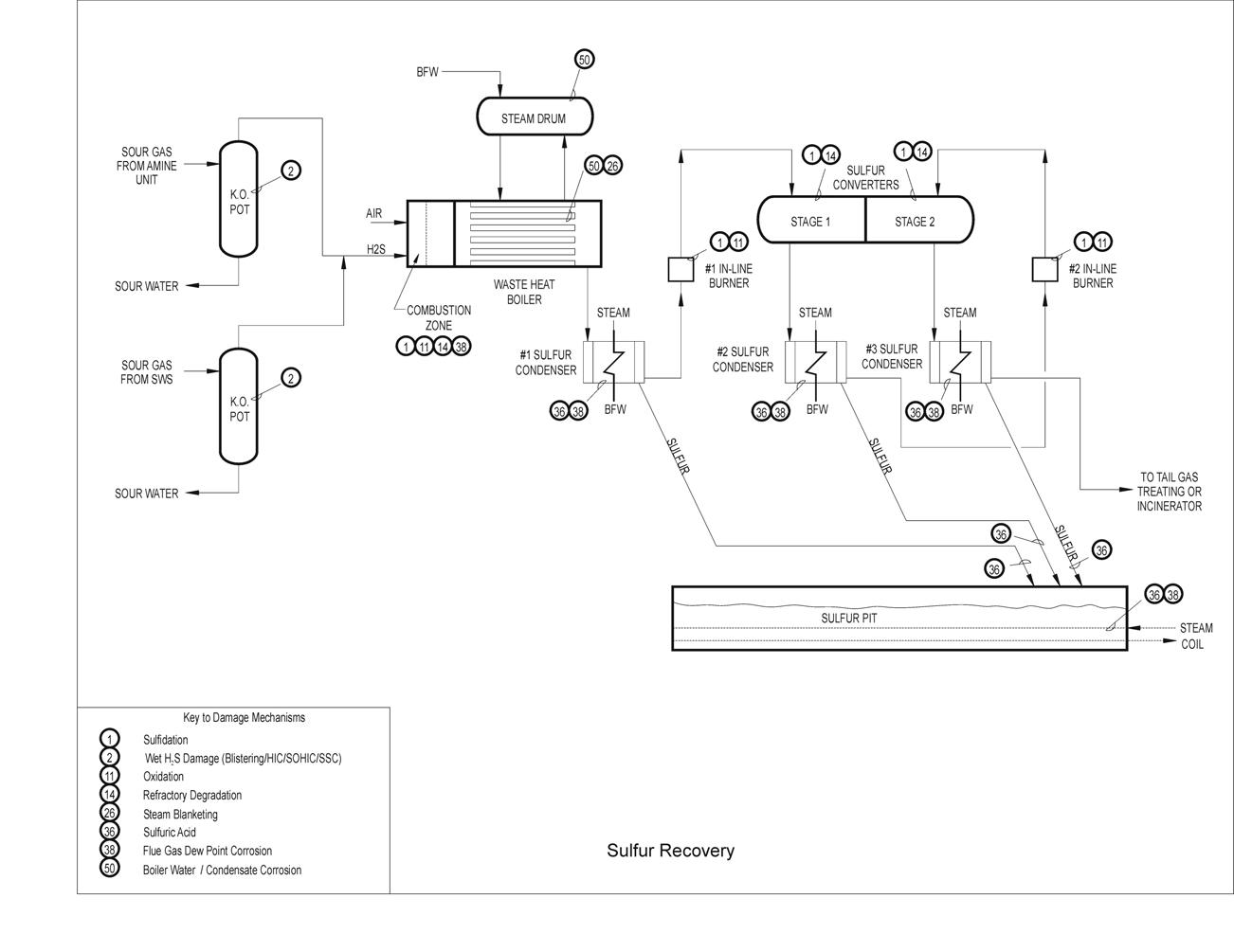
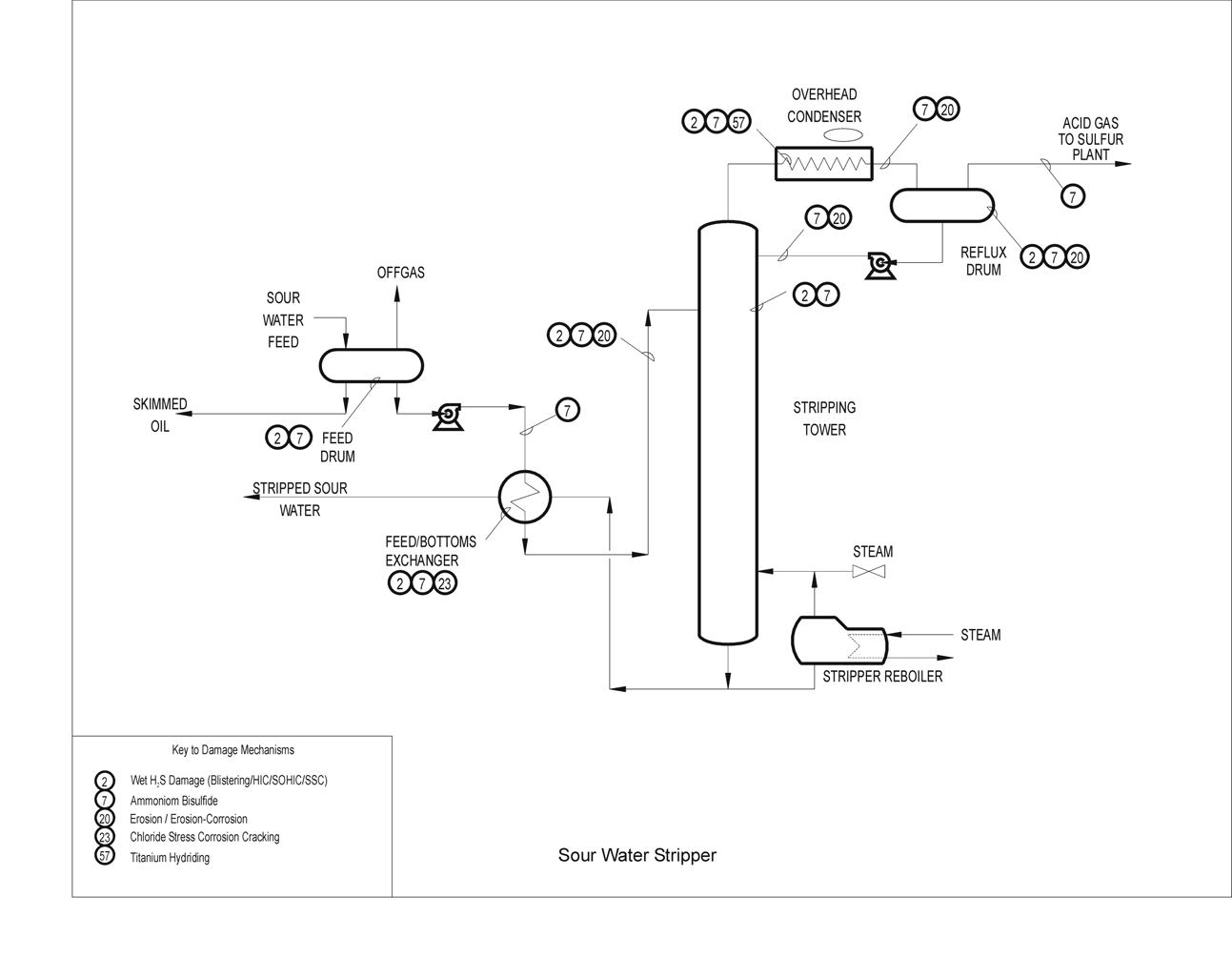
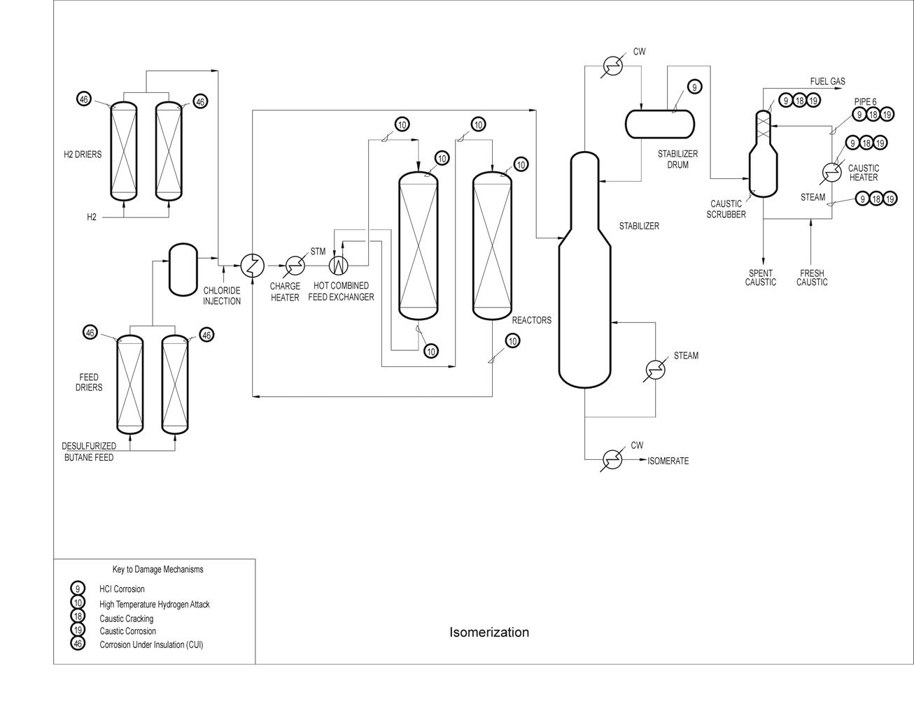
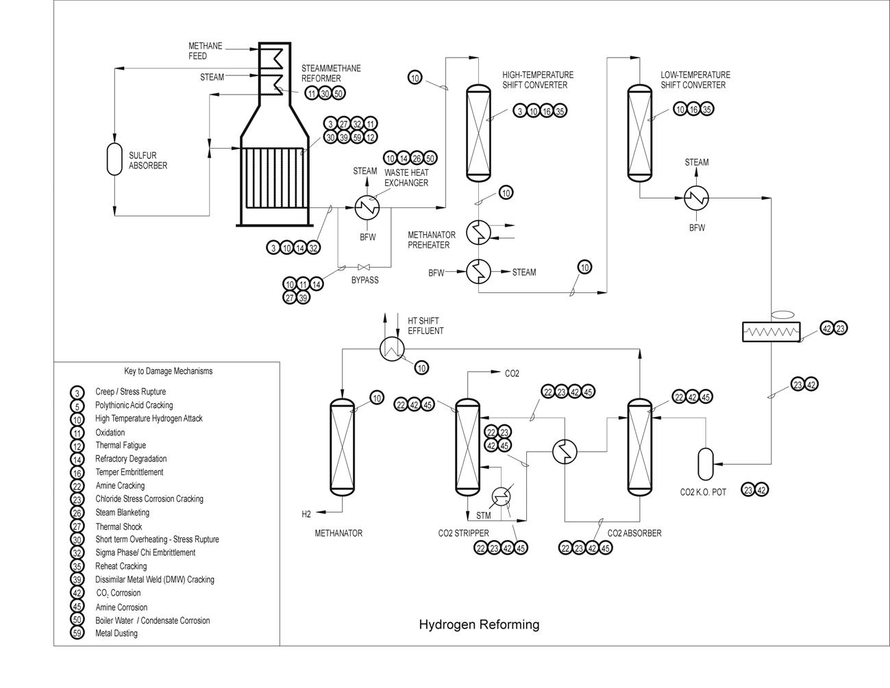
The NDE techniques provide ways to assess the integrity of a system or component without compromising its performance. These sensors are used to acquire information about the objects being tested and the information is converted into materials and defect parameters for performance and in-service life prediction. When it is possible to use several inspection techniques, the choice of a specific schedule will depend on the accuracy and cost of the inspection, balancing the money spent on safety measures with the business return of the system being maintained. The accuracy of a given technique must also be sufficient to detect defects considerably smaller than those that could result in failure because these defects can grow in size between inspections. The diverse nature of different NDE processes results in different sources of variance and possible impact on detection output capabilities. For example, a manually applied liquid penetrant process is dominated by the skill of the operator in process application and interpretation. An automated eddy current process is dominated by calibration, instrument, and procedure variances. It is important to recognize the source and nature of variance in each NDE process and to take such information into consideration when applying margins to the NDE processes.
Each method is dependent on different basic principles both in application and output, repeatable and reproducible NDE results depend on specific understanding and control of a series of parameters, such as:
Visual inspection is the oldest and most common NDE technique used to inspect for corrosion. It may be a quick and economical way of detecting various types of defects before they degenerate into failures. The physical principle behind visual inspection is that visible light is reflected from a surface, revealing some of its features. By observing the appearance of a component, an inspector can infer its condition. Surface corrosion, exfoliation, pitting, and intergranular corrosion may be detected visually when proper access to the inspection area is possible. Obviously, visual inspection can only detect surface defects. However, some internal corrosion processes do exhibit surface indications, such as pillowing or flaking.
Visual inspection and measurement of corrosion damage is desirable, but most frequently not possible without a system shutdown. However, in some instances it may be possible to use visual aids without unnecessarily shutting down the system, for example, by using borescopes or video cameras as described in the following sections. In a shutdown condition, access to vessels can be sufficient to make direct measurements of localized pitting depths with micrometers. In less accessible areas, such as tubes, a calibrated borescope may be used to make similar pit depth measurements
The reliability of visual inspection depends on the ability and experience of the inspector. The inspector must know how to search for critical defects and how to recognize areas where failure may occur. The human eye is usually very discerning and, with training, an operator can interpret images much better than any automated device. When necessary, permanent records can be obtained by photography or digital imaging. Visual inspection is often conducted using a strong flashlight, a mirror mounted on a ball joint, and a magnifying aid. Magnifying aids range in power from 1.5× to 2000×. Fields of view typically range from 90 to 0.2 mm with resolutions ranging from 50 to 0.2 μm. A 10× magnifying glass is recommended for positive identification of suspected cracks or corrosion damage.
The disadvantage of visual inspection is that the surface to be inspected must be relatively clean and accessible to either the naked eye or to an optical aid, such as a borescope. Typically, visual inspection lacks the sensitivity of other surface NDE methods. Visual inspection techniques can additionally be labor intensive and monotonous, leading to errors. However, compared to traditional NDE methods, such as eddy current and ultrasonics, visual inspections provide great advantage in speed of inspection and ease of interpretation. This is a significant economic advantage, as the downtime of the system being inspected is usually the greatest cost of performing NDE. Enhanced visual NDE methods attempt to provide similarly fast inspection while providing increased reliability over unassisted visual inspections.
A borescope is a long, thin, rigid rod-like optical device that allows an inspector to see into inaccessible areas by transmitting an image from one end of the scope to the other. Borescopes can get into tight places and provide reliable visual indications of internal surface conditions. Borescopes typically range from 6 to 13 mm in diameter and can be as long as 2 m. In general, the diameter of the borescope determines the size of the minimum opening into which it can be inserted. Certain structures, such as engines, are designed to accept the insertion of borescopes for the inspection of critical areas.
A borescope works by forming an image of the viewing area with an objective lens. That image is transferred along the rod by a system of intermediate lenses. The image arrives at the ocular lens, which creates a viewable virtual image that can be focused for comfortable viewing. Borescopes often incorporate a light near the objective lens to illuminate the viewing area. Different borescopes are designed to provide direct, forward oblique, right angle and retrospective viewing of the area in question.
The three main optical components of a borescope are the objective lens system, the relay lens system, and the eyepiece. The objective lens is located at the end of the borescope and it acts similar to a camera lens. It forms the primary image of an object on the back of the lens. Relay lenses reform or relay the primary image along the length of the borescope. In long borescopes, several relay lenses are used. The last set of relay lenses produce the final image at the eyepiece of the borescope. Each of these three components may produce a magnification and the total magnification is the product of each magnification in accordance with Eq.
Where Mb is the total borescope magnification, Mo the magnification of objective lens, Mr is the magnification of the relay lens, (usually 1), and Me = magnification of eyepiece.
The manufacturer determines relay lens and eyepiece magnification. The magnification of the objective lens is complicated by the fact that it varies with distance from the object to the objective lens and needs to be calibrated against a small object, such as a wire of known length positioned near the unknown defect. In specifying the magnification of a borescope, it is necessary to specify the distance of the object being observed since visual magnification is a logarithmic function of that distance. Magnification is highest at very close distances, decreases with increasing object distances, changes quickly at short distances, and then changes only slightly with increasing object distance.
The accuracy of defect image measurement depends on the probe-to-object distance and the operator ability to focus the instrument. Under ideal conditions, the measurement of image defects can be made to accuracy within 25 μm by using a special filar eyepiece. A number of light sources, UV, Vis, high intensity, and light-emitting diode (LED), are also available to aid viewing.
Fiberscopes are bundles of fiber optic cables that transmit light from end to end. They are similar to borescopes with the main difference that they are flexible and can curl into otherwise inaccessible areas. They also incorporate light sources for illumination of the subject area and devices for bending the tip in the desired direction (8). For fiberscopes, the image is carried from the objective lens to the eyepiece by a bundle of fiber optic cables, instead of by a rigid system of lenses. Light cannot escape through the side once it enters a fiber optic cable, so it follows the cable around twists and bends.
The ends of the fibers must occupy precisely the same respective positions at both the lens and eyepiece ends otherwise the image would be “scrambled”. The resolution of a fiberscope depends on the number of fibers and their diameter. More fibers of smaller diameter provide higher resolution, but they are also more expensive.
Video imaging systems (or “videoscopes”) consist of tiny charge coupled device (CCD) cameras at the end of a flexible probe. Borescopes, fiberscopes and even microscopes can be attached to video imaging systems. These systems consist of a camera to receive the image, processors, and a monitor to view the image. The image on the monitor can be enlarged or overlaid with measurement scales. Images can also be printed on paper or stored digitally to obtain a permanent record. Video images can be processed for enhancing and analyzing video images for defect detection. Specialized processing algorithms may be applied which could identify, measure, and classify defects or objects of interest.
Many companies now offer a complete, standalone video information processing system. Features of these closed-circuit television (CCTV) systems include defect image measuring capability, computerized video enhancement, alphanumeric keyboard for data identification, high-resolution display and recording, hardcopy documentation, and audio recording. Video imaging systems are ideal for applications involving long inspection periods, multiple operator viewing, or cases where complete documentation is required.
The liquid penetrant NDE method is applied to detect faults that have a capillary opening to the test object surface. The nature of this NDE method demands attention to material type, surface condition and rigor of cleaning. Liquid penetrant inspection can be performed with little capital expenditure and materials used are low in cost per use. This technique is applicable to complex shapes and is widely used for general product assurance. The basic stages of liquid penetrant inspection are illustrated in figure The surface to be inspected is first cleaned thoroughly to remove all traces of dirt and grease. A brightly colored or fluorescent liquid is then applied liberally usually by soaking the component during 20–30 min to allow the fluid to penetrate any surface-breaking cracks or cavities. After soaking, the excess liquid penetrant is wiped from the surface and a developer applied. The developer is usually a dry white powder, which draws penetrant out of any crack by reverse capillary action to produce indications on the surface. These colored indications are broader than the actual flaw and are therefore more easily visible.
A number of different liquid penetrant systems are used in industry. Fluorescent penetrants are normally used when the maximum flaw sensitivity is required. However, these penetrants must be viewed under darkened conditions with a UV lamp or black light, which may not always be practical. The most commonly used systems are solvent removable, or water washable, red dye systems.
Magnetic particle inspection (MPI) is applied to the detection of defects at or near the surface in test objects made of ferromagnetic materials when a magnetic field is applied to the specimen, either locally or overall, using a permanent magnet, or an electromagnet with flexible cables or hand-held prods. It cannot, however, be used to detect deeply embedded flaws, nor can it be used on non-ferromagnetic materials, such as aluminum, copper, or austenitic stainless steel.
The MPI is often used to look for cracking at welded joints and in areas identified as being susceptible to environmental cracking, such as SCC or hydrogen induced cracking, and other cracking mechanisms such as fatigue cracking or creep cracking. Wet fluorescent MPI finds widespread use in looking for environmental damage on the inside of vessels.
Magnetic particle inspection can be performed with little capital expenditure and, as with the liquid penetrant technique, materials used are low in cost per use, the technique is applicable to complex shapes, and is widely used for general product quality assurance. Magnetic inspection can be portable. It only requires a magnetization power source, such as is provided by an electrical outlet. It is most frequently used in evaluating the quality of the weld deposit and subsurface weld indications, such as cracks.
If the material is sound, most of the magnetic flux is concentrated below the surface of the component being examined. However, if a flaw is present, such that it interacts with the magnetic field, the flux is distorted locally and ‘leaks’ from the surface of the specimen in the region of the flaw. Material characteristics or surface treatments that result in variable magnetic properties may therefore decrease the detectability of defects.
Once a component is magnetized, fine magnetic particles applied to its surface are attracted to the area of flux leakage, creating a visible indication of the defect. The materials commonly used for this purpose are black iron particles and red or yellow iron oxides. In some cases, iron particles are coated with a fluorescent material enabling them to be viewed under a UV lamp in darkened conditions.
Magnetic particles are usually applied as a suspension in water or paraffin. This enables the particles to flow over the surface and to migrate to any flaws. On hot surfaces, or where contamination is a concern, dry powders may be used as an alternative to wet inks. On dark surfaces, a thin layer of white paint may be applied to increase the contrast between the background and the black magnetic particles. The most sensitive technique, however, is to use fluorescent particles viewed under a UV black light.
Magnetic particle inspections is particularly sensitive to surface-breaking or near-surface cracks, even if the crack opening is very narrow. However, if the crack runs parallel to the magnetic field, there is little disturbance to the magnetic field and it is unlikely that the crack will be detected. For this reason, it is recommended that the inspection surface is magnetized in two directions at 90◦ to each other. Alternatively, techniques using swinging or rotating magnetic fields can be used to ensure that all orientations of crack are detectable.
Permanent magnets are attractive for on-site inspection, as they do not need a power supply. However, they tend to be used only to examine relatively small areas and have to be pulled from the test surface. Despite the need of a power supply, electromagnets find widespread application. Their main attraction is that they are easy to remove once the current has been switched off and that the strength of the magnetic field can be varied. For example, an ac electromagnet can be used to concentrate the field at the surface where it is needed. Handheld electrical prods are useful in confined spaces. However, they suffer two major disadvantages that can rule out their use altogether. First, arc strikes can occur at the prod contact points and these can damage the specimen surface. Second, because the particles must be applied when the current is turned on, the inspection becomes a two-person operation.
In some cases, MPI can leave residual fields that subsequently interfere with welding repairs.
The concept of D-sight is related to the schlieren method (Schlieren methods evaluate the refractive index distribution inside a test section from the light deflection angle distribution) for visualizing index of refraction gradients or slopes in an optical system. D-Sight has the potential to map areas of surface waviness, as well as identify cracks, depressions, evidence of corrosion, and other surface defects. One possible problem with DSight is that the technique shows virtually every deviation on a surface, regardless of whether it is a defect or a normal result of manufacture.
D-Sight requires two operators. The first operator is responsible for positioning the inspection head on the surface being inspected. The second, the pendant controller, uses preplanned placements shown in the pendant to direct the first operator.
It can be used in direct visual inspection or combined with photographic or video cameras and computer-aided image processing. D-Sight systems usually consist of an inspection head containing the optics, video camera and light source, a computer with inspection planning software, and remote pendant with touch sensitive screen for controlling the acquisition process.
The acquired images are shown on the pendant touch screen. It is possible for the pendant controller to make an immediate assessment, but the recommended procedure is to postpone the image analysis and complete the acquisition process for the whole inspected surface. This reduces the time during which the system has to be available to the inspectors. The results of inspection may then be reported on wire-frame diagrams of the aircraft type, for example, and thus easily be referenced back to locate the detected damage.
The D-Sight imageprovides a direct comparison to the as-received and paint stripped views of the outer surface of the intact lap joint. As labeled this is a “transformed” compilation image made from four original D-sight. These images were collected after temporarily increasing the surface reflectivity of the lap joint by wetting with a fluid or “highlighting”.
When viewing the D-sight inspection image of the corroded lap joint shown in figure above, the overall deformation pattern is readily visible but the location that is different because it is smoother reveals the presence of a broken fastener with only the paint holding it in place. There are few inspection techniques that can find failed rivets before visual inspection notices them by their absence. Rivet M15 fell out when the paint was subsequently stripped.
The edge of light (EOL) enhanced optical technique is a relatively new approach to nondestructive inspection. It works by converting changes in surface slope into light intensity variation in an image. The optical path in the EOL scanner converts surface slope changes into light intensity variation. A light source behind a slit is used to produce a rectangular band of light on the surface of the object to be scanned. In the main zone of the band, the intensity is constant. At the edge, the intensity does not fall to zero immediately, due to diffraction effects, although it does drop off rapidly with distance. T
he detector of the EOL scanner is set up to operate in the middle of this “edge-of-light” zone of rapidly changing intensity. The detector is held at a constant position with respect to the light source, and records the light intensity reflected from the surface. The intensity of light is constant if the surface is smooth. A change in slope appearing in the edge zone changes the angle at which the light is reflected from the surface, which changes the location of the detector in the edge-of-light band, and therefore the intensity of light appearing at the detector.
The EOL has unique applications in the inspection of small-scale surface phenomena, and has been used for the detection of surface breaking fatigue cracks in turbine engine components, as well as for forensics applications. For many applications, EOL performs better than inspections using liquid penetrant, magnetic particle, ultrasonic inspections, optical microscopy, or even scanning electron microscopy.
The technique is relatively quick, with scanning speeds in the order of 2–20 linear cm s−1 and line widths of 10 cm or more. Additionally, EOL inspection results are easily interpreted since they closely resemble the actual subject.
Moire interferometry is a family of techniques that visualize surface irregularities. Many variations are possible, but the technique most applicable to corrosion inspection is shadow or projection moire. The structured light technique is geometrically similar to projected or shadow moir´ methods, and can be thought of as an optical straight edge. Instead of fringe contours being the resultant observation, the departure from straightness of a projected line is what is observed and analyzed. Using image processing techniques, the surface profile can be calculated.
Ultrasonic inspection or ultrasonic testing (UT), one of the most widely used NDE techniques, is applied to measure a variety of material characteristics and conditions. Ultrasonic examination is performed using a device that generates an ultrasonic wave with a piezoelectric crystal at a frequency between 0.1 and 25 MHz into the piece being examined and analyzes the return signal. The method consists in measuring the time it takes for the signal to return and the amount and shape of that signal.
The accuracy of ultrasonic monitoring is limited by variations of ultrasonic wave velocity in different metals, by temperature variations in the substrate, and discrimination of the acoustic reflections. Test objects must support the propagation of acoustic energy and have a geometric configuration that allows the introduction and detection of acoustic energy in the reflection, transmission or, scattered energy configurations. The frequencies of the transducer and the probe diameter have a direct effect on what is detected. Lowering the testing wave frequency increases depth of penetration while increasing the probe diameter reduces the beam spread. Increasing the frequency also increases the beam spread for a given diameter.
Manual scanning is performed using instruments that have an oscilloscopetype read-out. Operator interpretation is made by pattern recognition, signal magnitude, timing, and respective hand-scan position. Variations in instrument read-out and variations in scanning can be significant. Automated scanning is performed using an instrumented scanner that keeps track of probe position and automated signal detection such that a response map of the internal structure of the component can be generated.
Techniques have been developed to employ different types of waves, depending on the type of inspection desired. Compression or longitudinal waves are the type most widely used. They occur when the beam enters the surface at an angle close to 90◦. These waves travel through materials as a series of alternate compressions and dilations in which the vibrations are parallel to the direction of the wave travel. This wave is easily generated, easily detected, and has a high velocity of travel in most materials. Compression waves are typically used for thickness measurements and for the detection and location of defects that present a reasonably large frontal area parallel to the surface from which the test is being made, such as for corrosion loss and delaminations. They are not very effective, however, for the detection of cracks that are perpendicular to the surface.
Shear or transverse waves are also used extensively in ultrasonic inspection and are generated when the beam enters the surface at moderate angles.
Shear wave motion is similar to the vibrations of a rope that is being shaken rhythmically. Shear waves have a velocity that is about 50% of longitudinal waves in the same material. They also have a shorter wavelength than longitudinal waves, which makes them more sensitive to small inclusions. This also makes them more easily scattered and reduces penetration.
Surface waves or Rayleigh waves occur when the beam enters the material at a shallow angle. These waves travel with little attenuation in the direction of the propagation, but their energy decreases rapidly as the wave penetrates below the surface. They are affected by variations in hardness, plated coatings, shot peening, and surface cracks, and are easily dampened by dirt or grease on the specimen.
Lamb waves, also known as plate waves and guided waves, occur when ultrasonic vibrations are introduced at an angle into a relatively thin sheet. A lamb wave consists of a complex vibration that occurs throughout the thickness of the material, somewhat like the motion of surface waves. The propagation characteristics of lamb waves depend on the density, elastic properties, and structure of the material, as well as the thickness of the test piece and the frequency of vibrations. Lamb waves can be used for detecting voids in laminated structures, such as sandwich panels and other thin, bonded, laminated structures.
Ultrasonic inspection has been used for decades to measure the thickness of solid objects. A piezoelectric crystal serves as a transducer to oscillate at high frequencies, coupled directly or indirectly to one surface of the object whose thickness is to be measured. The time the wave of known velocity takes to travel through the material is used to determine its thickness. Since the late 1970s, ultrasonic equipment has been enhanced greatly by combining the basic electronics with computers. However, many instruments still in use today are for single-point thickness measurements, which do not provide the capability of the more sophisticated systems.
Rugged instruments based on portable computers are now available from many vendors. These systems, complete with motor-driven robotic devices to manipulate the transducer(s), have created the ability to measure wall thickness of corroded components at tens of thousands of points >0.1 m2, which can be converted into mass loss and pitting rates. This capability, coupled with increased precision of field measurements achievable with computer-controlled systems, has made these automated ultrasonic systems well suited for on-line corrosion monitoring. However, the sensitivity of even these sophisticated techniques generally excludes their use for real-time measurements.
Developments are now being made with individual transducers or transducer arrays that are left in place to provide continuous monitoring. Permanently attached transducers improve accuracy by removing errors in relocating a transducer to exactly the same point with exactly the same couplant thickness.
With proper transducer selection, equipment setup, and controlled temperature conditions, the accuracy of controlled ultrasonic inspection can exceed ±0.025 mm in a laboratory setting. Field inspections are typically to within ±0.1 mm. Robotic systems have permitted us to increase the precision of thickness reading by achieving more consistent transducer manipulation than can be accomplished with manual ultrasonic inspection.
Uncoated components having a smooth external surface after cleaning off any biomass or debris can be inspected for internal corrosion or erosion wall losses with the traditional single backwall echo approach. Through-coating measurements allow coated systems to be inspected without removal of the coating after applying echo-to-echo technique and A-scan imaging provided the coating is well bonded to the metal surface and its thickness <6 mm. The thickness of the metal substrate is determined simply by the TOF for the ultrasonic signal to reach the back surface and return to the transducer measured using either signal T2 or T3. The UT digital gauges with 4- to 5-MHz, dual-element transducers are able to inspect carbon steel or austenitic stainless steel for walls thicker than 1 mm. Dual-element transducers can focus the ultrasonic beam at a specific depth range thus enabling optimum sensitivity on corroded, eroded, or irregular internal riser surfaces. These transducers are highly sensitive to small pits in their optimum thickness range. External inspection for internal general loss or localized pitting without surface coatings or with coatings thinner than 6 mm typically involves marking the component surface into a grid pattern, followed by point-by-point ultrasonic thickness measurements of individual grid sections using manually manipulated measuring instruments. This tedious task often results in limited measurement accuracy. The costs and difficulties of this process are compounded by the need for inspection personnel.
The available combinations of equipment and techniques make UT well-suited for crack depth sizing over a wide range of industry applications. Ultrasonic length and depth sizing examinations are common on a wide variety of aluminum, carbon steel, and stainless steel components in industry. Less common materials, such as plastics and cast stainless steels, can also be examined with special equipment. In pulse-echo testing, a transducer sends out a pulse of energy and the same or a second transducer listens for reflected energy or an echo. Reflections occur due to the presence of discontinuities and the surfaces of the test article. The amount of reflected sound energy is displayed versus time, which provides the inspector information about the size and the location of features that reflect the ultrasonic wave. Ultrasonic sizing of the length and depth of defects is accomplished using a variety of transducers and techniques. For decades, the amplitude drop method was used for length and depth sizing. However, in the mid-1980s the amplitude drop method was proven to be accurate only for length sizing.
There is no one depth-sizing technique that is accurate through the full range of thicknesses encountered in industry. Multiple depth-sizing methods are normally utilized to assess crack depths accurately. Crack length sizing with the amplitude drop method can typically be performed using the same equipment that is used for crack detection. Accurate crack depth sizing often uses special transducers and calibrations. The crack is typically first classified as shallow, mid-wall, or deep, then accurately sized with the appropriate equipment for the applicable range.
Defect sizing with UT depends on specialized training and experience to provide relatively accurate and consistent results. Through-wall depth sizing accuracy of ±1.3 mm is normally achievable in the field.
Conventional UT is limited because the pulse-echo signal is strongly influenced by reflector type, shape, and orientation, and is not related just to size. A relatively recent development is what is called the time-of-flight diffraction (TOFD) method.
With TOFD, one transducer transmits an ultrasonic signal through the material being inspected. This signal is then received by a second transducer. This produces a single waveform or plot of signal amplitude versus time. If there is a defect in the material between the transmitter and the receiver, the ultrasonic signal will be diffracted and this will alter the waveform. The time of arrival of diffracted ultrasonic signals is used to calculate crack location and depth. Since identifying a flaw from a single waveform can be difficult, multiple waveforms or B-scans are “stacked” together to create a D-scan. The advantages of the TOFD method over other ultrasonic methods are that it allows large volumes of material to be inspected efficiently, produces permanent records of data, and reduces operator misjudgment and subjectivity.
The TOFD relies on the detection of forward scattered diffracted signals, as opposed to backward reflected or diffracted signals that are used in conventional pulse-echo ultrasonic inspection. For weld inspection, two transducers are used, one mounted on either side of the weld, with both aimed at the same point in the weld volume. The tests are conducted in a pitch-catch mode, with one transducer being the transmitter and the second the receiver. Broad beam transducers are used so that the entire weld is flooded with ultrasound and, consequently, the entire volume is inspected using a single uniaxial scan pass along the weld length.
Because the technique relies on detecting the forward scattered diffracted signals originating at the flaw edges, precise measurement of flaw size, location, and orientation is possible, and inspection reliability improves. Point reflectors are precisely determined by using geometric considerations, beam angles, and the appropriate sound propagation velocity. The TOFD has been accepted for the examination of critical components and welds in many industries such as fossil and nuclear power, petrochemical, oil and gas refineries, and pipelines.
Radiographic inspection methods utilize radiation in the form of either X-rays or other high energy rays, which can penetrate the material being inspected and be relatively absorbed depending on the thickness or the density of this material. Variations in the material can be detected by recording the differences in absorption of the transmitted waves. The variations in transmitted waves may be recorded by either film (radiography) or electronic devices (radioscopy) thus providing a 2D image that requires interpretation. The method is sensitive to any discontinuities that affect the absorption characteristics of the material.
The thickness of corroded piping and other equipment can be deduced from radiographic images in several ways. For example, the difference in optical density of the film in a noncorroded area of the image compared with the optical density in the pitted area can be correlated with the difference in thickness of the two areas, and thereby the depth of corrosion pits can be estimated. With repeated surveys of specific areas at intervals determined by the severity of the corrosion damage, the changing depth and area of corrosion can be resolved and corrosion rates approximated. The method can be used on-line, but is too insensitive to provide real-time measurements.
The radiographic technique can be used to determine the integrity of piping and equipment over large areas relatively inexpensively, using either manual techniques or automated, real-time radiographic inspection systems. This technique does not require access to the component being inspected, which means it can be used to inspect insulated, clad, bundled, or otherwise inaccessible components. However, absolute thickness of the inspected object is not normally discernible from the radiographic image. From the differential optical density of the film, a difference in thickness can be estimated, but the remaining wall thickness is assumed based on other information, such as the nominal wall thickness of the piping.
Advanced uses of radiography are being made with the aid of computers and complex algorithms to manipulate the data. This is termed computed tomography, or CT scanning. By scanning a part from many directions in the same plane, a cross-sectional view of the part can be generated, and the internal structure may be displayed in a 2D view. The tremendous advantage of this method is that internal dimensions can be measured very accurately to determine such conditions as wall thinning in tubes, size of internal discontinuities, relative shapes, and contours. More advanced systems can generate three-dimensional (3D) scans when more than one plane is scanned. Computed tomography scanning is costly and time consuming.
Tangential radiograpTangential radiography, also known as profile radiography, is used for detailed inspection of small pipe sections under insulation. From the contrast in the radiograph image, the thickness of the pipe wall can be measured for both edges of the pipe. In order to ensure complete inspection, successive measurements must be made while rotating the source and film around the circumference of the pipe. Among the drawbacks of tangential radiography is the difficulty of inspecting pipes with diameters greater than about 25 cm, radiation concerns that require care to ensure nearby workers are not exposed to unhealthy levels of radiation, and the expense of film. In addition, film-based tangential radiography is a slow process, requiring images to be acquired from many angles since only a small quadrant of the pipe can be inspected at one time.
Magnetic flux leakage (MFL) is the oldest and most commonly used in-line inspection method for finding metal-loss regions in gas-transmission pipelines. The MFL is typically used to detect metal loss due to corrosion or gouging, but can sometimes find other metallurgical conditions, such as inclusions or weld porosity. This technique is not well suited for detection of cracks or other long, narrow, or shallow defects. However, there may be some limited success finding deep circumferential cracks. It is useful for locating defects where volumetric material loss, such as pitting, occurs and it is a relatively fast technique for inspecting equipment with large surface areas, such as tanks, or long distances in the case of pipelines.
MFL technique uses a combination of permanent magnets and sensor coils to identify corrosion in steel tubes, pipes, and plates. Magnetic flux is channeled into the component being inspected between the opposite poles of two magnets. If there is a defect in the metal, some flux that leaks out may be detected and measured by the sensors positioned near the metal surface and between the magnets. Corrosion causes a decrease in the thickness of the wall, leading to flux leakage at both sides of the wall. At metal loss regions, a higher flux density is recorded. These changes in the magnetic field depend on the radial depth, axial length, circumferential width, and shape of the defects. The amplitude of the leaking flux is compared with results from known defects in similar materials after the inspection and the analyst then makes wall-loss estimates and predictions. The MFL has applications in tanks, heat exchangers, pipelines, and tubular products. Different types of MFL systems are used for these different applications. Some systems, such as in-line pipeline inspection tools, are very sophisticated self-contained systems that gather and store various data remotely. Signal analysis can be either real time or done at a later date, depending on the application and the inspection system.
Magnetic flux leakage can work through coatings of up to 10 mm thickness and is generally limited to pipe thicknesses of 12–15 mm. Above this thickness, it is difficult to obtain magnetic saturation. Typical wall thickness sizing accuracy is on the order of ±10% and length accuracy of ±1 cm with a 80% confidence level. It depends on surface cleanliness so that sensors have good contact with the part being inspected and sizing is impaired by noise signals produced by oxides and scale on the metal surface. In some applications, strong magnets can make moving the sensors difficult.
Eddy current (EC) testing uses the principles of electromagnetic induction to identify specific material characteristics and conditions. When an electrically conductive, but nonmagnetic material is exposed to an alternating magnetic field that is generated by a coil of wire carrying an alternating current, eddy currents are induced on and below the surface of the material. These eddy currents, in turn, generate their own magnetic field that opposes the magnetic field of the test coil. This magnetic field interaction causes a resistance of current flow, or impedance, in the test coil. Slightly magnetic materials, such as S41000 stainless steels, can still be examined using a magnetically biased probe that is used to neutralize the permeability effect on the eddy currents.
By measuring changes in impedance, the test coil or a separate sensing coil can be used to detect any condition that would affect the current carrying properties of the test material. Eddy currents are sensitive to changes in electrical conductivity, changes in magnetic permeability, geometry or shape of the part being analyzed, and defects. Among the latter defects are cracks, inclusions, porosity, and corrosion. The size of the defects and the detection limits are important. The EC is extremely sensitive to very small changes in the material structure, hence is capable of finding small discontinuities of <100 μm in highly conductive materials. Depending on the orientation of the defect being measured, an accuracy of ±5% of wall thickness can be obtained.
An EC system incorporates the electronic signal generator–processor and a probe containing at least one coil. The fields in the generator and sensor coils are balanced by adjustments of frequency, amplitude, and distance. A change in the balance of the two fields indicates various defects or material thinning.
Eddy current has several distinct advantages. First, the process does not require direct contact of the test probe to the specimen. However, the probe must be in close proximity to the test specimen in order to induce eddy currents in the specimen. The technique is fast when used for tube bundles inspection for which external access to tubes is restricted, a serious limiting factor for most other NDE techniques. In industrial and aerospace settings, the same system may be used to examine many different pieces of equipment. Another important advantage of eddy current NDE is that it requires only minimum part preparation.
Reliable inspections can be performed through a nonconductive coating up to thickness of about 0.4 mm. Inspection can also be performed very rapidly in production applications, as the technique is conducive to automation. The process requires a skilled operator to calibrate and interpret indications. Once the range of the inspected component conditions is known the system can be set for automated interpretation provided a reliable set of reference standards, preferably of production conditions, has been used to calibrate the system.
Eddy currents are fairly localized in the immediate region of the coil. The exact depth of penetration by eddy currents is dependent on the magnetic permeability and conductivity of a specimen, as well as the frequency of the ac probing signal.
Sophisticated, digitized, multichannel eddy current instruments are used extensively throughout industry. Computer-controlled robotic delivery systems to manipulate probes are used in areas such as manufacturing and nuclear power generation. Currently, phase analysis instruments provide both impedance and phase information. This information is displayed on an oscilloscope or an integrated LCD display on the instrument.
Another type of EC instrument displays its results on planar form on a screen. This format allows both coil impedance components to be viewed. One component consists of the electrical resistance due to the metal path of the coil wire and the conductive test part. The other component consists of the resistance developed by the inducted magnetic field on the coil magnetic field. The combination of these two components on a single display is known as an impedance plane.
Automated scanning is performed using an instrumented scanner that keeps track of probe position and automated signal detection such that a response map of the test object surface can be generated. The results of eddy inspection are extremely accurate if the instrument is properly calibrated. Most modern EC instruments in use today are relatively small and battery powered. In general, surface detection is accomplished with probes containing small coils (3-mm diameter) operating at a high frequency, generally 100 kHz and above. Low frequency eddy current (LFEC) is used to penetrate deeper into a part to detect subsurface defects or cracks in underlying structure. The lower the frequency, the deeper is the penetration.
Remote-field eddy current (RFEC) was developed in the 1950s and is widely used for inspection of metallic pipes and tubing. Its inspection is conducted by exciting a relatively large, low-frequency ac coil inside the pipe. A pick-up coil, offset by approximately two pipe diameters, can then be used to detect changes in the flux field due to the tube wall condition, thickness, permeability, and conductivity.
In operation, an electromagnetic field is transmitted into the pipe thickness. This direct path is attenuated rapidly to create circumferential eddy currents, which diffuse radially toward the outer wall. Once reaching the outer wall, the field spreads rapidly with little attenuation. This field then rediffuses back to the inner wall, interacting with defects in the remote field region, before being detected by the pick-up coil. Because this is a through-wall technique, defects at any depth in the pipe wall can be detected with similar sensitivities instead of just surface defects that can be detected by conventional EC.
In general, the wall thickness affects the phase between the excitation and detector signals, and the extent of the defect affects the amplitude. Although magnetic flux can be used to measure changes in thickness of both magnetic and nonmagnetic materials, it is generally used to identify defects in magnetic material for which eddy currents are not effective. Sophisticated multichannel digital instruments are now available to measure magnetic flux. The system is composed of electronics to generate, manipulate, and display the magnetic flux signals, and a probe to introduce the magnetic field into the component being inspected. Originally used to inspect oilfield tubulars for corrosion, it now has applications in small-bore tubes and in plate. Typical applications include inspecting heat exchanger and boiler tubes for corrosion or erosion.
Advantages over conventional EC include equal sensitivity to defects on either the inner or outer surface, insensitivity to probe wobble or lift-off, and not being limited by the penetration depth. However, RFEC is usually limited to the detection of wall loss. Attempts have been made to detect pits using differential receivers and multiple receiver coils, but the sensitivity is usually insufficient due to the interference of corrosion byproducts with signals from pits. Additionally, the speed of inspection using RFEC is significantly slower than with conventional EC testing.
Pulsed eddy current (PEC), another EC variant technology, employs the response to an input pulse instead of a sinusoidal wave to characterize the loss of material. The advantages of a PEC technique over conventional EC are its larger penetration depth, relative insensibility to lift-off, and the possibility to obtain a quantitative measurement result for wall thickness. This technology has been shown to measure material loss on the bottom of a top layer, the top of a bottom layer, and the bottom of a bottom layer in two-layer samples with an accuracy of about 5%. A mechanical bond is not necessary as it is with ultrasonic testing. The instrument and scanner are rugged, portable, and can use conventional coils and commercial probes.
Additionally, pulsed EC can detect of wall-thinning areas without the need to remove the outside protection coatings. The pulsed magnetic field sent by the probe coil penetrates through any nonmagnetic material between the probe and the object under inspection, for example, insulation material. The detected EC signal is processed and compared to a reference signal in order to eliminate the normal effects due to the material properties and a reading for the average wall thickness within magnetic field area results. This technique can be used for nominal wall thickness between 6 and 65 mm and insulation thickness <150 mm using transducers with a diameter between 50 and 100 mm.
Magneto-optic imaging (MOI) is provided by the response of a magneto-optic sensor to weak magnetic fields that are generated when eddy currents induced by the MOI interact with defects in the inspected material. Since its introduction, the use of MOI has steadily increased particularly in areas where it outperforms traditional methods, such as EC spot probes and sliding probes. Multiple tests have shown MOI to be a fast and reliable method of finding surface and subsurface cracks and sometimes corrosion in metal aircraft skins.
The magneto-optic/EC nondestructive testing instrument is based in part on the principles of Faraday magneto-optic rotation. In 1845, Michael Faraday first observed the effect when linearly polarized light was transmitted through a piece of glass placed in an external magnetic field. It was observed that magnetic fields affect optical properties of certain materials so that when linearly polarized light is transmitted through the material in the direction of an applied magnetic field, the plane of polarization is rotated.
A schematic of a MOI set-up is shown in figure b. A foil carrying alternating current serves as the excitation source and induces eddy currents in a conducting test specimen. Under normal conditions, the associated magnetic flux is tangential to the specimen surface. Defects in the specimen generate a normal component of the magnetic flux density that is detected by the magneto-optic sensor. The usual sensor consists of a thin film of bismuth-doped iron garnet grown on a substrate of gadolinium gallium garnet.
Images appear directly at the sensor and can be viewed directly or imaged by a small video camera located inside the imaging unit. The operator can view these images while moving the imaging head continuously along the area to be inspected. In contrast to conventional EC methods, the MOI images resemble the defects that produce them, making the interpretation of the results more intuitive than the interpretation of traces on a screen. Rivet holes, cracks, and subsurface corrosion are readily visible. The image is in video format, and therefore easily recorded for documentation.
Thermography is an emerging inspection technique that monitors the changes in the thermal patterns of an object as it is heated, cooled, or kept in a steady-state ambient condition. Thermography is becoming an increasingly popular NDE tool as equipment costs and computer technologies become more affordable and able to handle the large quantities of data generated by the thermographic equipment. Commercial thermographic equipment is available that can detect a 0.2◦C temperature difference in materials up to 500◦C. Beyond that temperature, a 2◦C difference is detectable for temperatures up to 3500◦C.
Thermographic inspection methods may be used to measure a variety of material characteristics and conditions. They are generally applied in the defect detection mode for the detection of interfaces and variation of the properties on interfaces within layered test objects. Inspected components must be thermally conductive and the test object surface must be reasonably uniform in color and texture. The method is a noninvasive area–volume inspection process and therefore loses resolution near edges and at locations of non-uniform geometry changes. Because it is an area-type technique, it is most useful for identifying areas that should be inspected more carefully with other NDE techniques offering a greater precision, such as EC and UT methods.
With a passive thermographic measurement system, the thermal camera images the IR energy radiated, scattered, and reflected from the surface of thematerial undergoing inspection. An embedded defect (corrosion pit or void) has a thermal emissivity that is different from the substrate material. Differences in thermal emissivity and thermal diffusion will be imaged as variations in image brightness, allowing damage to be detected and characterized.
In certain instances, the thermographic measurements can be made in a spectral bandpass window that allows the IR energy to propagate efficiently through a coating layer and probe the material substrate underneath, such being the case for typical US Air Force primer–topcoat paint combinations./
Recently, a process has been developed for IR imaging of subsurface defects by ultrasonically stimulating the component. In this technique, an ultrasonic transducer was coupled to the part and the ultrasonic energy from the transducer caused the defect areas to heat up. Consequently, these heated areas were detectable by the thermal imaging system.